July 31, 2015
What is cross-talk compensation in controls?
Provided by Julian Renz, HEIDENHAIN Product Specialist, Machine Tools
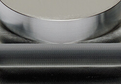
Figure 1: Stud on square, milled with CTC; no visible flat spot
Compensation of acceleration-dependent position errors at the tool center point leads to better machining results
When feed axes are accelerated, machine components can be deformed or begin to oscillate because of inertia forces. For example, if the spindle head of a gantry-style machine is accelerated in y-direction and then decelerates to stop at the designated position, the machine components in motion (i.e. the spindle and its components) tend to overshoot in the same direction (y-direction). This leads to deviations at the Tool Center Point (TCP), which can lead to inaccurate workpieces.
However, if the feed forces are not in line with the center of gravity of the y-axis, mechanical coupling causes the axes perpendicular to the y-axis to oscillate as well (x- and z-axis). These pitching movements are called “cross talk” at HEIDENHAIN.
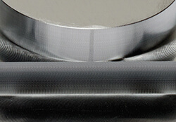
Figure 2: Effect of elastic deflection (the overlarge stud is flattened when the square is milled)
A control feature called Cross-Talk Compensation (CTC) can significantly reduce deviations at the TCP for the primary oscillations in feed force-direction and for the pitching movements. CTC allows achieving a high surface finish without the need to slow down the feed
rate in order to stay within tolerance. Only HEIDENHAIN offers this CTC function.
Milling of a rectangular stud after a circular stud on top was milled first
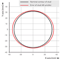
Figure 3: Accuracy of the circular movement. The deviation from the nominal contour is shown enlarged 500-fold
As shown in Figure 1, CTC is active and the circular stud has no surface cuts. In contrast, Figure 2 (CTC inactive) shows that a little piece is cut off the circular stud.
An explanation for this is illustrated in Figure 3, which shows the tool path and deviations from it as measured with a cross grid encoder.
In the case with CTC active, the circular stud is machined more like an ellipse instead of the programmed circle. This is because the machine overshoots as acceleration values are changed. Thus, the protruding piece of the circular stud is cut off (as shown in Figure 2) as the cutter moves along the rectangular stud underneath.