June 15, 2021
Taking control of cost of ownership in semiconductor production machinery
When it comes to component selection for semiconductor equipment, the name of the game is often cost of ownership. In other words, how long and how well it will perform as designed out-of-the-box and installed into the system, and ultimately, uptime. Semiconductor work is so precise and delicate, that the slightest instability of an image scanner or a compounding delay in move, acquire, measure (MAM) time can require a diagnostic pause and ultimately up drives the cost of ownership.
This makes the ability for a motion control system to maintain high performance over time, while resisting wear caused by the environment and activity, invaluable. The accuracy, resolution and throughput demands also prevent the use of some protections like inductive or sealed encoders. This makes careful component selection crucial. Yes, a component can, indeed, lessen the cost of ownership of expensive machinery used to work on semiconductors. Let’s touch on some of the factors to consider when building motion systems for the semiconductor industry.
Making the most of “useful” time
The time spent on collecting measurement data, acquiring images, patterning, is useful time. The time spent on wafer loading/unloading, pre-alignment and motion between imaging, measurement or inspection sites needs to be minimized to maximize tool productivity.
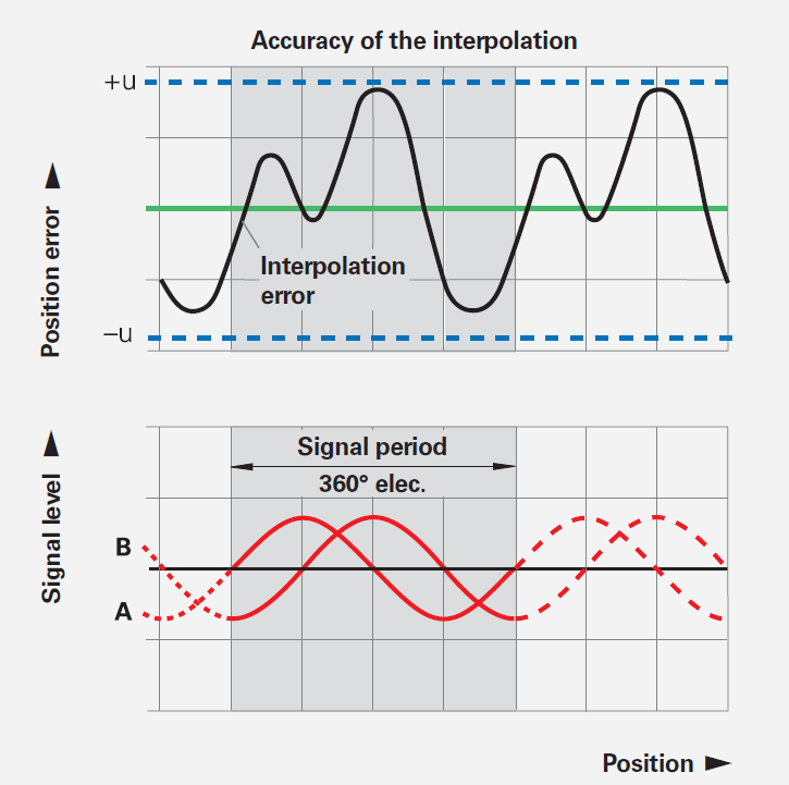
One example is a linear scale’s interpolation error, which affects the efficiency of linear motors—the lower the error, the better the constant velocity. So, if you’re scanning a camera over a wafer, or wherever you need constant velocity, low error improves the image-taking quality of the machine.
The accuracy of interpolation is ascertained with a serially produced measuring standard and is indicated by a typical maximum value u of the interpolation error. Encoders with an analog interface are tested with a HEIDENHAIN electronic device (e.g., EIB 741). The maximum values do not include position noise and are indicated in the specifications.
Interpolation error
The accuracy of the interpolation is mainly influenced by:
- the size of the signal period
- the homogeneity and period definition of the graduation
- the quality of scanning filter structures
- the characteristics of the sensors
- the quality of the signal processing
Interpolation error isn’t the only “naturally” occurring imperfection that must be accounted for to ensure each millisecond is maximized.
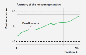
The accuracy of the measuring standard is indicated by the uncompensated maximum value of the baseline error. This accuracy is ascertained under ideal conditions via measurement of the position errors with a serially produced scanning head. The distance between the measuring points is equivalent to the integer multiple of the signal period. As a result, interpolation errors have no effect. The accuracy grade a defines the upper limit of the baseline error within any section of up to one meter in length.
Accuracy of the measuring standard
The accuracy of the measuring standard is mainly determined by:
- the homogeneity and period definition of the graduation
- the alignment of the graduation on its carrier
- the stability of the graduation carrier
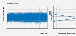
The amount of position noise depends on the signal processing bandwidths necessary for forming the position values. It is ascertained within a defined time interval and is stated as a product-specific RMS value.
Position noise
Position noise is a random process leading to unpredictable position errors. The position values are grouped around an expected value in the form of a frequency distribution. In the speed control loop, position noise influences the speed stability at low traversing speeds.
Sustaining high precision over time
Accuracy and resolution specifications of standalone components are one thing, but if the components can’t maintain those performance characteristics within a fully integrated system, they will only add to the cost of ownership of machinery. Each component must be considered within the larger system they’ll be part of. Especially in high-throughput environments, this introduces factors like temperature, contamination and wear.
Part of the resistance to this depends on the engineering of the system, how everything fits and works together. We’ll take a look at that first, through the lens of one of the most important variables: temperature. Then, we’ll explain some of the different motion control technologies to keep an eye out for. Technologies that not only make the engineering process easier, but also deliver ongoing, above-and-beyond performance value.
Engineering for environmental variables (as seen through one variable: temperature)
Say you are imaging an area—point-to-point movement, complete stops and fixed in a position for a certain amount of time with only a small amount of acceptable imposition. The motor may be able to move to a position quickly enough, over and over and over again, but if it’s sized wrong and the machine doesn’t stop, the heat will generate thermal expansion and introduce unacceptable inaccuracies.
That expansion can have a huge impact on encoders. How quickly you’re able to go from place to place involves closed-loop control. If that signal is noisy and the resolution is too low, the electronics can’t perform calculations at the bandwidth or speed that it’s capable of therefore performance inevitably degrades.
The thermal behavior of your encoders are essential criterion for the working accuracy of the machine. As a general rule, the thermal behavior of the linear encoder should match that of the measured object. During temperature changes, encoders should expand or contract in a defined, reproducible manner. The graduation carriers of HEIDENHAIN encoders have differing coefficients of thermal expansion, so you can select the encoder with the thermal behavior best suited to your application.
Finally, imagine bearings as railroad tracks on a hot summer day, where slight deformation can cause a slight meandering of train cars from right to left. The same effect is possible, in this high-throughput world, if bearings aren’t ideally specified. As a result, maybe images you’re trying to take of a substrate are now kind of swaying from side to side. (That’s not to mention the wear and tear a motor’s attraction force can impose on poorly selected bearings, but we’re staying focused on temperature here.)
What to look for in motion control components
Smart engineering can lessen the cost of ownership of a semiconductor machine, and so can identifying priorities and seeking out the ideal solution. With almost no room for error in this industry, the best equipment has built-in value, often solving something that’s next to impossible to engineer for or a complication to avoid on a system level.
Low-wear designs and materials
Optical scanning encoders provide the best accuracy and resolution available. Most HEIDENHAIN encoders utilize the photoelectric scanning principle, which is performed contact-free. This method detects even extremely fine graduation lines down to a width of only a few micrometers and generates output signals with very small signal periods without inducing any wear.
An example of low-wear designs used on the metrology and inspection side would be our MRP angle encoder. Ideal for rotation positioning of substrates, these assemblies combine high-resolution measurement technology with a dependable high-precision bearing. The functional assemblies of both bearing and the encoder are harmoniously integrated with fewer components and fewer joints than alternatives. Such a highly integrated assembly can be rigorously tested (guideway accuracies, wobble, reproducible and non reproducible error) and specified, eliminating risk.
The integrated rolling bearings have been adapted specifically to the requirements of high-precision rotary axes. They are more rigid by a factor of at least 10 compared with that of air bearings of similar size and all but and eliminate the need for separate development of a rolling or air bearing.
The feedback assembly is one thing, but all electronics within encoder should have some resistance to wear built and designed in as well. One example, there are ways to reduce wear within the light source itself. Through extensive testing, we’ve the best led possible LED that can dissipate heat and maintain bright light for long periods of time. Our R&D people qualified every LED characteristic of the top LED brands and models to identify the most stable and durable lights for these applications.
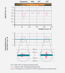
Measuring standard with contamination and the associated signal amplitudes with conventional scanning and scanning with the HSP 1.0 signal processing ASIC
Self-correcting scanning and/or signals
The HSP 1.0, signal processor ASIC continuously monitors the scanning signal and compensates nearly completely for fluctuations in signal amplitude. If the signal amplitude decreases as the result of contamination on the scanning reticle or measuring standard, the ASIC reacts by increasing the LED current. The ensuing increase in LED light intensity barely raises the noise level, even in the case of strong signal stabilization.
Embedded resistance to contamination
The smallest bit of contamination when moving at the speeds in the envelopes semiconductor machinery does, can be like hitting a pothole at 100 miles an hour. That’s why exposed encoder scales should have some resistance to contamination, even in highly regulated clean rooms.
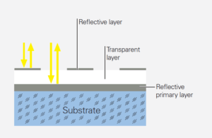
For this reason, we always recommend tough graduations. Very specialized manufacturing processes make this possible. In the OPTODUR and SUPRADUR processes, a transparent layer is first applied onto the reflective primary layer. To maintain an optically three-dimensional phase grating, an extremely thin, hard chromium layer is applied at a thickness of only a few nanometers.
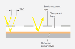
The graduations for the imaging scanning principle exhibit a similar design and are manufactured in the METALLUR process. A reflective gold layer is covered with a thin layer of glass. On it are chromium lines acting as absorbers. Since they are only several nanometers thick, these lines are semitransparent.
These types of graduations have proven to be particularly robust and insensitive to contamination because the low height of their structure leaves practically no surface for dust, dirt or water particles to accumulate.
Rigorous testing and detailed results
There should be little to no guesswork when building systems so complex. No matter what you’re specifying or who you’re buying it from, you must know the real, documented numbers and how they were arrived at. While most can’t match our testing capabilities and resources, here are some examples of the extreme R&D you should keep an eye out for if you’re in the semiconductor business.
Electromagnetism
Dr. Rasher in Germany is affectionately known as the “lightning bolt guy” throughout our global subsidiaries. His job is to test the limits of what bursts, surges, fields or electrostatic discharges may have on encoders. Using specialized equipment, he shoots 5-10″ bolts of static electricity at our encoders to see how they react to electromagnetic spikes.
Cable durability
We have dedicated machines that test the limits of cable twisting, pulling and bending force. Those have been running for at least 12 years now, completing 100 millions of cycles.
Vacuum compatibility
More than 50 percent of semiconductor equipment now operates in a vacuum. When selecting feedback devices for this environment, components need to be tested and developed with these kinds of factors in mind:
- Careful consideration of the epoxies and materials of the drum and scanning unit so as to limit the amount of residual gas in the vacuum chamber.
- Scanning units designed with vents to allow air to escape.
- Tin-plated copper outer shield for cabling, with a 15-pin vacuum rated connector to plug into the firewall feedthrough.
- Production and packaging should be done on a verified clean production line. Ours devices are baked out to 100°C for 48 hours before being put inside vacuum-compatible packaging with two layers, the outer layer being nitrogen flushed. Residual gas data in the vacuum chamber is actually displayed in the brochure of the encoder.
Keeping this kind of factors in mind, feedback devices can now be designed to handle vacuum environments down to 10-7 mbar without sacrificing high resolution and accuracy.
Vibration resistance
On the encoder front alone, we put dozens under constant stress in extreme environments for months at a time. We can supply you with the methodology and results of all kinds of tests like these; because we know how crucial getting what you expect is to improving cost of ownership, among other things.
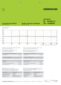
In fact, each and every HEIDENHAIN linear encoder comes with a Quality Inspection Certificate that confirms the specified accuracy grades of each encoder. The calibration standards ensure traceability to recognized national or international standards, such as required by EN ISO 9001. For advanced encoder series, an additional calibration chart documents the ascertained position error over the measuring range. It also specifies the measuring parameters and the measurement uncertainty.
That said, each motion component should be carefully vetted in the design phase and after instillation. And we certainly haven’t accounted for all the variables out there. Let us help you sort out your next motion control challenge. We can help you get there with the confidence that your creation will pay off as expected, long after it powers on for the first time.