July 22, 2020
How to find the right encoder for a servo motor
Servo motors are a kind of direct drive motor that, generally speaking, pack a lot of power into a component that doesn’t need to take up a lot of space. On average, they 2-3 times more rated torque and 5-10 times more rated torque over short periods. This makes them ideal for high-tech machinery and systems we rely on. Specifically, they provide significantly more continuous power and rated torque of short periods and higher torque at higher speeds than other motor types.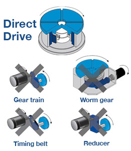
You’ll notice, there isn’t any mention of accuracy, resolution repeatability. That’s because these kinds of motors rely specifically on a feedback device that observes mechanical motion, changes of position, its rate and signals it to the control. The feedback device also receives control signals. While there are a few feedback options, if accuracy, resolution and repeatability are of any importance to the application, the encoder should be chosen carefully when deciding which motor to select.
What to know about the application
First and foremost, understand where and how the motor and encoder will be applied. Understand what factors could help or hurt the cooperation of the two, its efficiency and/or durability. If you understand the variables of an application, there’s an encoder solution that fits just right.
Environmental conditions
Temperatures, moisture, shock and vibration, contamination all present risks to systems, especially encoders that often include delicate glass scales. If any of these factors come into play, you’ll also want to consider sealed encoder options or explore the wide variety of flexible mounting options. For example, inductive encoders are typically contactless and bearingless solutions that use the change in mutual inductance between the sensor and scale to create a signal. This makes inductive encoders more resistant to contamination, like dust and moisture, along with increasing their ability to handle vibration and shock.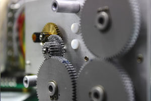
Physical configuration/mounting method
Some encoders can incorporate a shaft, in which case it is assembled with the drive unit by means of a coupling. While enabling proper alignment, the coupling also isolates the sensing element from a drive unit, both mechanically and electrically. Form factor, physical distance between encoder and controllers and mounting tolerances are important to consider—and there are all kinds of options for addressing them—when mounting and encoder to the motor/system assembly.
Magnitude of the motion and sensitivity to rehoming
high precision automotive gear box close-up.Gear box for increase and reduce speed. precision gear box assembly with servo motor, rotary index
Incremental encoders are electromechanical transducers that track incremental advances from some arbitrary home position set at start up. If they are shut down or fault out, they must be re-homed prior to operation. For simple applications that just need speed control on a web processing line, for example in a package handling facility, an incremental encoder can be an economical solution.
Absolute encoders, on the other hand, assign a unique digital word to each angular position. The encoder can always return the angular position of the device being tracked when interrogated, even at start up. The best fits for absolute encoders include applications for which re-homing at any point in the cycle could result in damage or unsafe conditions. Examples include surgical robots, automotive robots, or interrelated mechanics or axes that could crash upon power up after a fault. In some cases, just the time spent rehoming can negatively impact productivity and justify the modest cost differential of an absolute encoder.
The electrical requirements of your system
All the feedback data in the world will not benefit the system if it can’t be sent from the encoder to the readout. Incremental and absolute encoders generate different output, so their wiring and transmission schemes are different. Incremental encoders require each channel to be wired directly to the control/counter device. There are two basic wiring approaches.
Single-ended wiring
This is when one wire from each channel to the readout device, plus wires for Vcc and ground. Less wiring means lower cost, fewer points of failure and error. This arrangement is, however, vulnerable to noise and is best used when cable runs are short.
Differential wiring
This alternative uses a twisted pair, two wires from each channel to the readout device, plus wires for Vcc and ground. While the added complexity increases cost and opportunities for error, this arrangement is ideal for applications with high noise or long cable runs.
Incremental encoders require output drivers to transmit the signal to the readout device. The choice of output driver should be driven by the requirements of the receiving device. What are the voltage requirements for your controller/drive? The voltage needs to be high enough to be read and strong enough to survive transmission across the network.
Resolution, repeatability and accuracy
 Choice of resolution is one of the bigger pitfalls of specifying an encoder. There’s a widespread assumption that a higher resolution encoder will automatically increase positioning accuracy. That’s not necessarily the case. The accuracy of any positioning system is limited by the mechanics. Even the highest resolution encoder will be ineffective if there is so much compliance in the system that it can’t reliably position to the accuracy required. Customers sometimes confuse the concepts, thinking that higher resolution means that their system is more accurate when actually it just means you can see more.
Need some help selecting an encoder or motor for your next big project? Our engineers are here to help you find a motion control solution from across the HEIDENHAIN Family of Brands. Get in touch with us today.