April 21, 2011
NEW encoders for high speed spindles
 by Michael Martin
Product Marketing Engineer
Spindles are among the key components of a machine tool. Their characteristics are determined by the design, the drive and the bearing systems. Position feedback encoders play a decisive role particularly for the drive performance. HEIDENHAIN is presenting the NEW ERM 2400 encoders, ideal for applications that offer little space and yet require a relatively high accuracy of angular measurement.
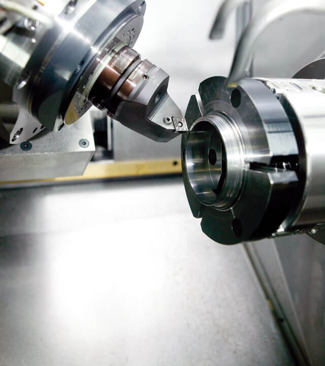
The increasing complexity of workpieces makes higher accuracy necessary on spindles and position encoders.
The trend continues in machine tool building toward increasingly compact machines with ever greater performance. The requirements are increasing both for productivity and for machining quality. This means that engineers strive for both a high stock removal rate in roughing operations as well as very high accuracy and flawless surface quality after finishing operations. Moreover, different and frequently changing operating conditions are confronted in day-to-day operations because part production usually involves small batch sizes. But the greater complexity of workpieces is also driving requirements on machine tools.
Specializing in machine tools
To enable machine tools to work very efficiently and precisely, this has to be considered in the machine technique and its mechanical design. This is why direct drives are now becoming common for feed axes. The benefits of direct drive technology are low wear, low maintenance, and higher productivity. Direct drives have long been characterized by their compact design.
The benefits of direct drives also apply when they are used for spindles. Because there is no need for mechanical transmission elements, the drive chain is very rigid and backlash-free, making its movements highly dynamic and precise. They can therefore achieve higher performance and speeds than conventional drives. This is the only opportunity to exploit today’s cutting materials and enable a more economical cutting process. At low speeds, other positive effects of direct drive technology become apparent. The absence of mechanical transmission elements makes it possible to attain higher accuracy by reducing hysteresis and elasticity error.
The increasing complexity of workpieces also intensifies the need for higher accuracy in spindles. It is not unusual for certain machining movements to be achieved only through the interaction of feed axes and the spindle. For example, when manufacturing a thread, a single-point tool needs to assume a defined angular attitude.
High rigidity and its results
The absence of mechanical transmission elements also means that the signal quality of the encoders has a stronger effect on positioning and drive performance. The velocity controller, for example, calculates nominal current values using position information directly from the encoder. These values are then processed to accelerate or decelerate the drive. Even small deviations of the position information result in unsteady drive performance and additional heat generation by the spindle. In some cases this increases running noise.
This increases the importance of the encoder and its signal quality. The size of the grating period greatly influences the signal quality and interpolation error. Measuring systems using coarse mechanical graduations, such as gears, are increasingly losing significance and being replaced by encoders with higher accuracy. While the optical encoders with their fine graduations are more suited for low shaft speeds (typically less than 2000 rpm), the magnetic modular rotary encoders are ideal for spindles (Figure 1). The signal period of approx. 400 µm and the special process for applying the graduation enable the encoders to achieve accuracies and shaft speeds to fulfill increasingly challenging requirements for spindles.
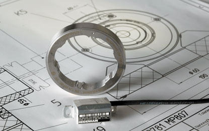
Figure 1 – The new series of magnetic rotary encoders was conceived specially for spindles in machine tools.
For example, a drum outside diameter of 64.37 mm provides 512 signal periods per revolution. Gears with comparable dimensions, however, have a significantly smaller number of grating and signal periods. The interpolation error of the magnetic modular encoders, as with many other HEIDENHAIN encoders, remains significantly better than 1% of the signal period. This means that together with the smaller signal period, the encoder has a considerably lower, absolute interpolation error and therefore distinctly better output signals for calculating the motor’s nominal current. The result is greater speed stability.
Harsh environments
The encoder in the machine tool is often exposed to heavy loads from cooling lubricants and chips. Sealing is made more difficult by the high spindle speeds on motors and relatively large diameters. An encoder is therefore required with low sensitivity to contamination. This is why the ERM magnetic modular encoders (Figure 2) are particularly well suited with their rugged design. They can even operate under high humidity, heavy dust loads, and in oily atmospheres.
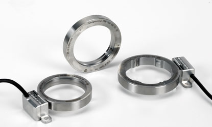
Figure 2 – The ERM 2400 series encoders consist of a scanning head and a circumferential-scale drum. The latter is available with smooth inside contour or with a keyway as anti-rotation element.
For years, the stability of their signals under contamination has been making the ERM the preferred encoder for C axes on lathes. In addition, their large inside diameters eliminate constraints from the encoder in the machining of bar material. But spindles in milling machines place even higher demands with respect to rotational speed and dimensions than in lathes. In most cases, previous magnetic modular encoders were not able to meet these requirements.
New generation of modular encoders
HEIDENHAIN is therefore presenting a new generation of magnetic modular encoders in which new ideas have been realized to achieve smaller dimensions and higher permissible shaft speeds. The ERM 2400 encoders are ideal for applications that offer little space and yet require a relatively high accuracy of angular measurement. They consist of two main components: the scale drum and the scanning head (Figure 1).
The scale drums are available in two versions. The inside of the ERM 2404 scale drum is smooth (Figure 2). Only a friction-locked connection (clamping of the drum) is to be used to prevent it from rotating unintentionally. The ERM 2405 scale drum features a keyway that serves as an anti-rotation element (Figure 3). Like the ERM 2404, it requires a force-fit connection to fasten the drum. The special shape of the drum’s inside is designed to ensure that, in spite of the keyway, high shaft speeds are permissible even during reciprocating traverse.
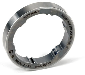
Figure 3 – The scale drum of the ERM 2405 with keyway.
The inside diameters of the ERM 2400 series scale drums are large in relation to the outside diameters. For example, the scale drum with an outside diameter of 64,37 mm has an inside diameter of 40 mm. The drum width is 11 mm, which, like the clamp fastening of the drum, also has a positive effect on space requirements.
A magnetized steel alloy serves as the graduation carrier. Scanning the graduation of north and south poles produces signal periods of approx. 400 µm. In addition, a reference mark signal is magnetized onto a separated track in order to provide an absolute reference. The absolute position on the scale drum, established by the reference mark, is gated from either direction with exactly one measuring step.
The scale drums are slid onto the mating shaft during installation. The scale drum is centered via the centering collar on its inner circumference. In order to keep the eccentricity of the graduation to the bearing and the concomitant additional error resulting from mounting to a minimum, the inside diameter is designed to leave only a small amount of play between the centering collar and the recommended mating diameter of the spindle. This makes it possible to easily and quickly remove the scale drum for servicing, for example after spindle bearing damage due to collision. The scale drum is clamped by mounting elements fitted to the individual design. Here the clamping force is applied annularly to the scale-drum surface.
The scale drums are designed to allow high mechanically permissible shaft speeds. With a drum outside diameter of 64.37 mm and a smooth drum inside surface, the maximum permissible shaft speed is 42,000 rpm. Extreme load conditions were assumed when specifying the maximum permissible speeds. This covers applications running continuously at the maximum permissible shaft speed as well as the even more demanding cases in which the maximum permissible speed is exploited in reciprocating traverse. For this type of speed behavior, 107 load reversals were applied, thereby suiting the requirements for fatigue strength.
Also, the new scanning head with its compact dimensions is ideal for applications in which installation space requirements are critical. The permanent magnetic graduation on the scale drum is scanned by magneto-resistive sensors in the scanning head (Figure 4). These sensors consist of resistive tracks whose resistances change in response to a magnetic field. The special geometric arrangement of the resistive sensors and the manufacture of the sensors on glass substrates ensure a high signal quality. In addition, the large scanning surface allows the signals to be filtered for harmonic waves. Typical subdivision accuracy values are therefore significantly better than ± 1 % of the signal period.
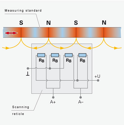
Figure 4 – The encoder signal period is approx. 400 µm. Additionally, a reference mark is magnetized onto a separate track.
Besides the version with sinusoidal output signals, a version is offered with purely serial position value output over the EnDat 2.2 interface. In this version, the incremental scanning signals are converted in the scanning head into purely serial data words. This conversion includes a 14-bit interpolation that provides ideal conditions for servo control. In addition, the EnDat 2.2 interface offers a large number of advantages, such as automatic self-configuration and a high degree of safety in signal transmission. As with all incremental encoders, the absolute reference is detected by scanning two reference marks. A scale drum with distance-coded reference marks is required in order to make it possible to “home” the encoder in this version.
Installing the scanning head is simple and fast because it can be aligned and fastened to the scale drum with the aid of a spacer foil. If the recommended mounting tolerances are complied with, it is not necessary to inspect the output signals or readjust them.
Encoders are gaining ground
The continuously growing requirements for productivity and machining quality are driving a trend toward more direct drives on spindles. However, the lack of mechanical transmission elements increases the influence of the encoders and their signal quality on positioning and control loop performance. The available installation space near the spindles remains very limited. For this reason, demand has been increasing for encoders that combine high signal quality with compact dimensions. Additionally, the encoders have to be designed for high shaft speeds. All of these demands are met by the ERM 2400 series modular encoders. Because they also feature a contamination-resistant scanning principle, they are ideal for use in spindles.