January 27, 2012
Importance of mounting tolerances for modular encoders
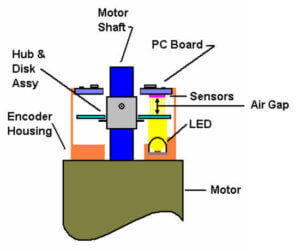
Figure 1: Encoder Installed on a Motor
Modular encoders are very susceptible to mounting misalignment. Since modular encoders have no bearing, they rely solely on the accuracy of the motor and encoder manufacturing process. If the motor dimensions are not within the mounting specifications or the encoders physical dimensions are all near tolerance limits, then the encoder may not operate correctly. There are several factors, which are of primary concern when mounting modular encoders.
Concentricity of the encoder housing with the shaft centerline is an important factor to consider. The encoder housing holds the LED and the sensors and positions them relative to the shaft centerline. If the concentricity error is too great, the lines on the disc will not line up correctly with the sensors, which can cause an increase or reduction in counts and the loss of the index or commutation channels.
Perpendicularity of the motor shaft centerline to the mounting surface can affect the gap relationship between the disc and the sensors. If the encoder housing is rotated relative to the motor shaft, the space between the disc and sensors can change, affecting signal amplitude and quality. The change in the gap will be dependent on the placement of the photo head on the mounting surface. Disc rotation will not affect the gap distance once the housing is secured.
Axial endplay of the motor shaft will cause the disc to move toward or away from the pc board sensors. The encoders are designed to handle small amounts of axial and radial run out, but if the axial run out is too large, the encoder disc can contact the sensors which may damage the lines on the disc or the sensors on the pc board. The perpendicularity of the shaft and mounting surface must also be taken into account when dealing with axial end play. The perpendicularity error must be added or subtracted depending on whether the perpendicularity error increases or decreases the gap between disc and sensors.
Tolerance between the encoder hub and disc assembly and the motor shaft affects the disc alignment to the sensors. If the inside diameter of the hub is at its maximum tolerance and the motor shaft at its minimum tolerance, this may affect the encoders output. An encoder in this situation will also be more susceptible to variations due to temperature changes.
Radial run out of the shaft will cause the data tracks under the sensors to be non- concentric. This can cause the index or commutation outputs to become non-functional.
Mounting the encoder according to the specified mounting tolerances can ensure proper operation and will likely allow the encoder to remain in service longer. For more detailed information about mounting specifications or for an example of how mounting stack ups may affect encoder performance, please contact us.