June 15, 2021
How to design long-lasting, precision feedback into semiconductor production machinery
It’s one thing to find something that works. It’s another, to find something that works, can keep up with the high demands and resist wear and tear. There’s only one chance to get as much of that right as possible, in the design stage where the necessary components are identified and specific ones are chosen.
There may not be a better example of this than the high-precision, high-yield world of semiconductor production. For maximum productivity and efficiency the control, the motor, the machine frame, and the position encoder must work seamlessly together. In this high-stakes sector, the potential costs of a misfit or a component that can’t hold up can have dramatic effects that trickle down through the whole engineering process or production itself.
From fabricating integrated circuits, wafer dicing and packaging testing, robotics need to move to designated positions rapidly, accurately and without overshoot or ringing. This makes direct-drive servo motors a popular choice. Their superior speed and control, however, put steep demands on feedback signals, putting a premium on encoders for short- and long-term performance. 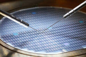
Clean, precise position feedback reduces vibration in the machine frame, eliminates velocity-dependent motor resonances, and prevents additional heat generation, allowing the motor to realize its maximum mechanical power rating, and efficiency of operation.
At semiconductor-level of precision, encoder signals need be interpolated to reach a high enough resolution for useful feedback. Interpolation error is to be anticipated with any encoder. That is, periodic position error within one signal period of the encoder’s output signals. Even the highest quality encoders, those most often applied in these scenarios, include interpolation error, though just 1-2 percent of the signal period. That said, if the frequency of interpolation error increases too much during production, resulting heating or noise can make it difficult for the drive to stay within its effective range.
If this naturally occurring error has this much impact on motor efficiency, and needs to be accounted for, just how important can the choices we actually have make? You guessed it, a lot.
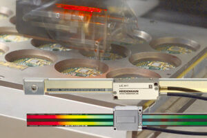
Optical scanning encoders are most often the best option in semiconductor production, but they are not created equal. These incorporate measuring standards or scales with periodic structures known as graduations. The substrate material is glass, steel, or—for large measuring lengths—steel strips. These fine graduations—periods from 40 µm to under 1 µm are typical—are manufactured in a photolithographic process. Seek out high-edge definition and excellent homogeneity. They are prerequisites for accurate performance.
The optical scanning is often paired with exposed encoders, meaning the measuring standard is exposed. These can reach higher levels of accuracy and resolution and take up less space. Even in fabs or inspection facilities where federal clean standards are adhered to, at such precision demands, contamination can still affect feedback (e.g. fingerprints from mounting or oil accumulation from guideways), and poor results will soon follow. While their homogeneity and definition impact accuracy, the toughness off the gratings affects contamination resistance.
 As an example, HEIDENHAIN uses tough gratings manufactured in highly specialized, proprietary processes. In our SUPRADUR process, a transparent layer is applied first over the reflective primary layer. Then, an extremely thin, hard chrome layer is applied to produce a grating. These graduations have proven to be particularly insensitive to contamination because the low height of the structure leaves practically no surface for dust, dirt or water particles to accumulate. This ensures an enduringly high signal quality that direct drives require.
Contamination on the measuring standard influences the light intensity of the signal components, and therefore the scanning signal. Its level of effect depends on the scanning method. Large, single-field scanning is the best choice. With only one field, the output signals will change in their amplitude, but not in their offset and phase position over the range of travel. They stay highly interposable, and the interpolation error remains small. The large scanning field (one of the largest scanning fields we deploy in semiconductor work is 14.5 mm2) in relation to the graduation detail reduces sensitivity to contamination. Even with contamination up to 3 mm in diameter, encoders continue to provide high-quality signals with position error below the values specified. This stable signal, even in the face of some contamination, maintains low interpolation error, high traversing speed, good control-loop performance and low heat in the drives.
Just like feedback has to resist contamination, it has to be able to handle temperature changes to remain within the machine’s working accuracy. The “operating temperature range” is the limit of ambient temperature within which the specifications of the encoder still comply, for one, thermal expansion of the encoder’s carrier. An encoder’s specified expansion coefficient should expand or contract in a defined, reproducible manner, matching the thermal behavior of the machine frame.
The thermal dynamics of the machine should be taken into account when deciding where to mount the encoders scale and scanning head. Don’t put feedback near heat sources. Still more reason why semiconductor machines must be designed with feedback in mind from the very beginning: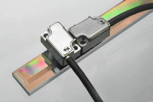
- The mounting surface must meet flatness requirements.
- To facilitate adjustment of the scanning head to the scale, the scanning head should be fastened to a mounting bracket.
- To keep the resulting Abbe error as small as possible, the scale should be mounted parallel to the machine guideway.
- To avoid vibration, the best mounting surfaces are solid and stable machine elements as opposed to hollow parts.
Finally, on mounting, with very small signal periods come very narrow mounting tolerances for the scanning gap, the space between the encoder’s scanning head and it’s scale. This is the result of diffraction caused by the grating structures. Such diffraction can lead to a signal attenuation of 50 percent upon a gap change of only ±0.1 mm.
More workable mounting tolerances are possible with encoders that use an interferential scanning principle and innovative index gratings, a variation of optical encoders that use the imaging principle to measure displacement.
Last, but not least, there are just a few wear considerations in the design phase for encoders. These include the bearings in encoders with integral bearing, the radial shaft seal rings in rotary encoders and angle encoders, and the sealing lips on sealed linear encoders. For reference, the scanning heads of exposed encoders feature protection ranging from: IP67 to IP40.
Semiconductor production simply cannot be successful without lasting precision feedback. And that starts with the encoders you choose. Demands can be so extreme that each detail of the encoder should be carefully considered, from the graduations on the scale to how the encoder is affixed.
If it all sounds a little daunting, that’s what we’re here for. We work at the nanometer level every day in all kinds of applications and settings. Our semiconductor engineers look forward to the chance to discuss your unique design challenges. Secure an online consultation spot, we’d be happy to try and help.