August 4, 2021
What makes a CNC control good for moldmaking [6 factors]
More and more, mold makers rely on high-speed cutting. Whereas EDM was once the clear choice, CNC machines have proven capable of not only meeting the necessary tolerance and finish requirements, but also streamlining processes. The right control plays a big part in accomplishing all of this.
The CNC isn’t the limiting factor in determining feed rates anymore, the mechanics of the machine are. And with mechanics like simultaneous 5-axis machining more accessible than ever, the right combination of machinery and control can be game changing for a business.
CNC control requirements for moldmaking
So, what do you need to look for in a control to take full advantage or machining capability and deliver precise, well-finished molds? First and foremost, the control should use an approach that is optimized for the milling machine and the manufacturing process. That is, the CNC control has features to either automatically smooth the axis movements or allow the operator to manually set tolerance limits.
Not only does moldmaking require precise control of both acceleration and deceleration along a programmed contour, but also compensation. For example, to properly compensate for a ball-nose end mill as the part or the tool pivots, the control should have some ability to dynamically adjust the cutter vector in X, Y and Z. Keeping the tool’s contact point constant is one of the only ways to achieve demanding finishes.
We’ve identified 6 areas that make a big difference. Let’s break it down.
Spatial plane function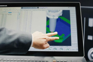
Many mold cores or bases require five-sided machining without excessive coordinated movements. The CNC should have a spatial plane function that allows the machinist to set the plane that is machined on each side of the part. That way, the machinist can program each side of the part in an X-Y-Z plane without changing the CAM program and ultimately improve the tolerances between features on each side.
Contour deviation monitoring
The control directs axis movements to follow the 3D surfaces within predefined tolerance bands that consist of simple line segments. The control should be able to automatically smooth the block transitions while the tool moves continuously on the workpiece surface. An internal function that monitors the contour deviations controls that automatic smoothing. This function enables the user to define the maximum-allowed contour deviation. The default value is defined by the machine tool builder in a machine parameter of the control (typically 0.01 to 0.02 millimeter).
The tolerance also affects the traverse paths on programmed circular motions. This is particularly important if the core or cavity has cylindrical details, which a user machines with either an interpolation milling or a mill-turn function.
Linear encoder compatibility
The CNC control should be able to ensure that all machine axes follow the exact path when moving from X-plus to X-minus and then moving from X-minus to X-plus after a step over. In other words, there must be exact reproduction of adjacent paths after cutting direction reversal.
Vibration mitigation
A machine axis moving very fast and changing direction on a point or a using a higher-than-permitted feed rate for the cutting tool can generate vibration, which impacts part quality. The CNC control should be able to monitor any type of tool vibration caused by either high dynamic movements or higher-than-permitted feed rates, and then adjust feeds and speeds to avoid chatter marks on the final part.
Operator flexibility
The CNC interface should allow for optimizing the machine dynamics based on each part’s feature priorities. The control should allow the operator or programmer to verify and optimize the program on-the-fly. Consider, for example, several different components made on the same machine, each with different accuracy, surface finish and lead time requirements.
Automatic feed and speed adjustments
Milling through mold cores or cavities with variable workpiece thicknesses is another machining challenge. A solution is a CNC that can detect how much material is currently cut, so the feeds and speeds can be automatically adjusted without operator intervention. This is accomplished with sensors connected to the CNC that measure spindle load and vibration, and then identify and adjust speeds and feeds within milliseconds. This technology ensures that the machine maximizes chip removal rate, based on workpiece cutting tool engagement, and cutter and spindle life.
Mold maker finds solution for vibration
Windsor Mold group handles high mix, low volume situations daily, making large molds for everything from automotive fascia to exterior applications. They use the mold-friendly HEIDENHAIN TNC 640 in the shop. When deciding on a control they performed tests combining the Active Chatter Control (ACC) and Adaptive Feed Control (AFC) features to see if it could help manage vibration and achieve very high material removal rates.
“You could actually feel the difference coming from the machine,” machining manager, Bill Minello, said. “It was unbelievable how much of a difference it was making.”
Large machine tool builder switches to the TNC640 control
TARUS builds some of the biggest machine tools in the world. They recently switched the controls they put on the machines they sell to their automotive, aerospace and mold & die customers to the TNC 640 from HEIDENHAIN. TARUS is now predominantly using the TNC 640 on its large high-performance machines because its cutting and performance went through a thorough testing process and performed even better than expected, as well as the fact that many in their main markets now require the HEIDENHAIN controls.
Looking for more advice on machining? Check out our CNC control magazine, Klartext.