October 20, 2012
Encoders for brushless motor commutation

by Tom Wyatt
Marketing Manager, North America
The process of steering current through the appropriate motor windings in order to produce an output torque is called commutation. Before start-up permanent-magnet three-phase motors must have an absolute position value available for electrical commutation.

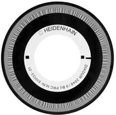
Figure 1: Rotary disk with serial code track and incremental track.
Several solutions from HEIDENHAIN make this possible, the first of which are absolute rotary encoders.
Single-turn and multi-turn versions provide the absolute position information immediately after switch-on. The exact position of the rotor is known, therefore, can be used for electronic commutation.

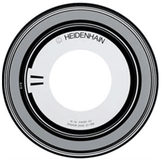
Figure 2: Electronic commutation can also be performed with incremental encoders.
Electronic commutation can also be performed with incremental encoders. For sine /cosine encoders we apply a second track referred to as a Z1 track (C&D).
The Z1 track produces a single sine and cosine signal per rotation in addition to the incremental signals. For sine commutation, rotary encoders with a Z1 track only need a subdivision factor and a signal multiplexer in the subsequent electronics in order to produce the absolute position. Additionally, speed and position information will be derived from the incremental track.

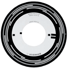
Figure 3: Block commutation disk.
The third commutation method is accomplished with an incremental rotary with what is called block commutation, U, V and W.
These encoders are available with various commutation tracks. Typical versions provide 3- signal periods at 120° mechanical or 4-signal periods at 90° mechanical per revolution. Independent of these signals there are also incremental signals used for position and velocity control.
The block commutation signals are transmitted as square-wave signals at TTL levels.
Figure 4 depicts 3-standard commutation configurations.

Figure 4: 3-standard commutation configurations.

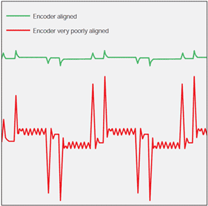
Figure 5: encoder alignment
Regardless of the method used, synchronous motors require rotor position information immediately following switch-on. When these encoders are mounted, the rotor positions of the encoder must be assigned to those of the motor in order to ensure the most constant possible motor current. Inadequate assignment to the motor EMF will cause audible noise, heat and high power loss. Refer to Figure 5.
HEIDENHAIN also offers diagnostic systems and tools that aid the commutation process.
It is important to note that the RENCO brand offers block commutation with their modular rotary encoders. Additionally, HEIDENHAIN linear scales of the LIC and LC product lines are used for commutating linear motors. These linear systems provide the exact position upon power-up. This makes it possible to start with maximum holding load on vertical axes, even at a standstill.

