January 15, 2018
Condition monitoring systems and the importance of the encoder
By Bob Setbacken, Product Manager, Leine & Linde
Whether you are operating a mine, a mill or a power plant, the goal is to generate expected yields and associated revenue. These factories or plants operate continuously to meet their targets. Downtime that is experienced from unplanned failures accounts for lost productivity, and overall costs rise as the difficulty of repair, access, and planning for support equipment contribute to the issues. The use of Condition Monitoring (CM) systems can and do help prevent these kinds of problems.
CM systems are implemented in order to provide continuous information about the operating state of equipment, making it possible to predict and prevent any impending mechanical or electrical damage in real-time. They monitor the state of the machine using meaningful physical variables either continuously or at regular intervals. They are typically made up of equipment components such as sensors, controls and rotary encoders that monitor vibrations, temperatures, humidity, shaft speed, or condition of lubricant, for example. A rotary encoder equipped with sensors beyond the traditional shaft position measurement capability can be especially useful in CM systems.
Rotary encoders within CM systems are generally located on assets that are 1) intrinsic to the efficient operation of the plant and 2) already communicating with the primary control systems. By adding the ability to bring additional process information, such as vibration, temperature, position and velocity, a CM system gains intelligence with a minimum increase in overhead.

The best CM systems make real-time comparisons with reference measurements, enabling operators to draw conclusions about the actual condition of gears, generators, roller bearings, rotors and other components. Such monitoring allows plant managers to plan or adjust maintenance intervals and set priorities, enabling optimum planning of maintenance schedules, personnel and materials.
This can have a significant impact on spares inventory. When items are purchased only when needed rather than on a Preventative Maintenance (PM) schedule that is based upon some historical aggregate or rules of thumb, the carrying costs of holding unused materials are eliminated. In addition, historical order programs do not allow for unexpected failures, so materials may not, in fact, be available when actually needed.
CM Applications That Make Sense
Wind, gas, or hydroelectric turbines are all examples of major capital assets that clearly benefit from CM. These installations must be capable of reliable and consistent operation in order for the supply of energy to the grid to be planned efficiently. Detecting system degradation prior to failure allows for preparation and performance of maintenance during off-peak periods, if possible, or at least at a known and planned point in time. The difference between pro-active and reactive repair scenarios in such cases can be as much as 5X in time to return to service and 10X in expense.
Typical CM systems can cost between $6-15K per installation. When considering that the asset being monitored can have operation lifetimes of decades beyond their warranties, it’s easy to justify investing in CM by preventing just one catastrophic repair during the out-of-warranty period. For a wind turbine, estimates for a down-tower gearbox repair are $220,000 or more. Advance notice prior to failure might allow the gearbox to be serviced up-tower prior to failure at a significantly lower cost.
 In the mining industry, electromechanical shovels for open-pit mining are huge mobile machines used to load haul trucks. Usually, the shovel-to-trucks ratio is about 1-to-12, so unexpected shovel downtime has a huge impact on production. Clearly, these shovels are prime candidates for CM systems. In the case of a large earth-moving shovel in Chile1, the types of physical variables a CM system might track include:
- Vibration measurement on key structural components
- Dynamic strain measurement
- Shaft velocities on motors
- Accelerometers on motors and transmissions
- Angular position measurements
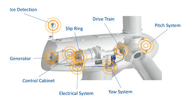
Wind Turbine Sensors, Courtesy of Leine & Linde Systems
In a wind turbine, similar measurements must be made, including:
- Vibration and strain measurement on blades
- Blade pitch and hub rotation speed
- Atmospheric data
- Vibration of generators and gearbox
- Strain gages on main structural components
- Incremental encoders on the main generator
- Temperature information on generators and gearbox
- Oil particulates and water content
- Yaw motor positions, temperature, and vibrations
If not managed properly, the addition of all these new sensors can cause infrastructure issues due to cabling, power management, and data acquisition demands. For example, measurements made in a motion control application might include the motor temperature, speed, angular or linear position, vibration, time in motion, moving/stop indication, sensor supply voltage, drive current and more. Quite a few sensors would be needed to gather all this information, and if they were discretely connected they would take quite a few I/O ports and associated processing time to monitor. This might be improved if the slowly varying measurements were all integrated onto a sensor bus, but there would still be many devices to connect. To help minimize this impact, fieldbus technologies are available that simplify the cabling and interconnect. In combination with a PLC, the collection process can automate and concentrate these measurements so that downstream controls are not overwhelmed and cabling is significantly reduced.
Measurement of slowly varying information, such as temperatures, water content in oil and humidity, can be handled over relatively low speed low cost communication systems such as AS-i, Modbus, or Foundation Fieldbus. These measurements are then collected by a PLC or similar controller and passed on to the main supervisory system.
For measurements with higher dynamics, such as vibration in a shaft or strain in a wind turbine blade, the large number of sensors used for data collection require a higher bandwidth bus capable of transferring larger amounts of more complex information.
For example, roller bearings are typical items where failure can be catastrophic and pre-failure maintenance can have a significant benefit. As a result, rotational speed and associated vibration and temperature are some of the physical variables most often measured. Vibration measurements can be made on a pre-determined schedule using portable equipment, but more and more often, sensors are being dedicated to the measurement point and accessed via some type of industrial network. Using a databus such as CAN, DeviceNet, Ethernet/IP, EtherCAT, Profinet or Profibus, measurements might go to the CM system, and in addition to a safety controller or a process control supervisory system.
An Encoder with Integrated Diagnostics
Using a rotary encoder with integrated diagnostics in a CM system is one of the best approaches for detecting vibrations of bearings and shafts, temperature, speed and position in a motor. In addition to minimizing the additional sensor requirements, these encoders can also pass this additional information up to the motion controller as part of the command/response data-stream. Currently, encoders utilizing the EnDat 2.2 bus system provide some of these capabilities. For example, the encoder self diagnostics, angular acceleration of the motor rotor, synthetic limit signals, motor and encoder temperatures can be included in the motion-control data packets. Although this does simplify the physical routing of the data, the motion controller must then peel this information off from the motion control information and use resources to pass this on up to the CM system.
One of the best possible solutions is a rotary encoder capable of supporting the highly dynamic requirements of motion control, or generator commutation, and in addition can support the requirements for CM. As the encoder must be there anyway, the more it can be leveraged to support additional purposes such as CM the better. Encoders are now available which provide position outputs suitable for motion control, and in addition provide diagnostic and commissioning information via Profibus DP or Ethernet.
The Leine & Linde Model 862 is just such an encoder. The 862 is a rotary encoder that provides several levels of CM support to the systems manager:
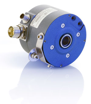 Walk-by visual alarms on the encoder housing consisting of Red/Green LED indicators provide an immediate visual verification that the encoder and monitored variables are within limits.
- The Advanced Diagnostic System (ADS) continuously monitors the encoder health and reports problems to the supervisory control via an alarm. The maintenance operator can then, with the help of a PC and analysis software, communicate with the encoder to establish the cause of the indicated fault. The operator is informed of the frequency, internal temperature and operating period at the time of the fault, as well as total operating time and the max./min. operating temperature. Output signals from the encoder can also be compared with the signal that is generated in the cable to detect a short condition in the interconnection.
- With Profibus DP capability, the diagnostic information is enhanced to support the requirements defined in the PROFIBUS-DP specification as well as encoder-specific diagnostic data. This includes device identification, operating status and alarms, encoder type identification, resolution and number of turns counted for multi-turn absolute devices. Also available are details on supported alarms and warnings, operating time, serial number and software versions.
- With an Ethernet connection, the 862 rotary encoder’s ADS-Online system provides the ultimate in diagnostic capability. With this system, many of the measurements previously discussed are integrated into the encoder, directly providing the asset manager with detailed information on the motor, generator, or other piece of equipment. Over an Ethernet connection to a PC or PLC, vibration, temperature, frequency, shaft speed, and supply voltage are available. There is also the ability to set custom warning levels. These can be used to ensure that vibration in the system never reaches damaging levels, frequency and shaft speed never reach over-speed or standstills, and to ensure that the machine does not overheat. Programmable warning levels can also be used to detect voltage drops in the power supply, or to generate an automatic warning when the encoder reaches a certain operating time. This data is stored continuously in the encoder at user specified time intervals, allowing for analysis of trends for vibration, temperature and more when needed by the CM system.
Because the encoder is so closely coupled to the primary drive or generator, measurement of temperature, vibration and other variables within the encoder itself gives a good overall picture of the health of the system. When these encoders make this information available via advanced databus communications directly to the CM system, overall efficiency of the maintenance system is improved.
1Mining References: Author Information: Daniel Ramírez, CADETECH S.A. Chile Tel: +56 41 2621500
https://www.ni.com/en-us/innovations/case-studies/19/cadetech-improves-monitoring-of-electromechanical-shovels-at-worlds-largest-copper-mines.html