October 5, 2011
Aspects of energy efficiency in machine tools
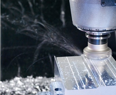 Discussions of the efficient use of energy have become more frequent in many sectors of industry. Machine tools comprise numerous motors and auxiliary components whose energy consumption can vary strongly during machining. The main spindle drive, for example, and the coolant system work near their rated power during roughing with a high stock-removal rate, while the power consumption during finishing is significantly lower. There is a very close interdependence between the individual components and subassemblies of a machine tool and aspects of productivity and quality. From a detailed examination of manufacturing processes to the power consumption of individual components, potential for savings can be evaluated and measures can be defined for the efficient use of energy.
In many branches of the investment goods industry, energy efficiency has developed into an important product characteristic. Geared motors for materials handling technology have been divided into efficiency classes for some time now. A multitude of ideas has been tried for increasing energy efficiency in manufacturing with machine tools. Potential savings result with regard to the base load of machine tools that require energy consumption even in nonproductive phases. The base load is determined substantially by the auxiliary components of a machine. Besides the use of energy-efficient motors in the auxiliary components, many possibilities for reducing the base load can be found in proper energy management. With energy management, consumers are specifically switched off by the machine control in nonproductive phases.
Measures to support the operator during setup also increase energy efficiency, because they shorten nonproductive phases and reduce the influence of the base load. Scrap inevitably increases energy consumption per good part. Manufacturing with accuracy starting from the very first part can therefore become a decisive factor for the energy efficiency of a machine tool. Machine designs with balanced thermal behavior and precise position measuring technology have a distinct advantage here.
Energy demand during milling
The power requirements of a milling process are divided into the following consumer groups:
- Cooling lubricant processing
- Compressed air generation
- Electrically powered auxiliary components of the milling machine
- CNC control package with main spindle and feed axis motors
The proportionally calculated energy for lighting, ventilation and air conditioning is added to these groups. The energy demand of a milling process strongly depends on the size of the milling machine and the machining task.
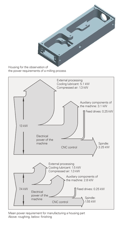
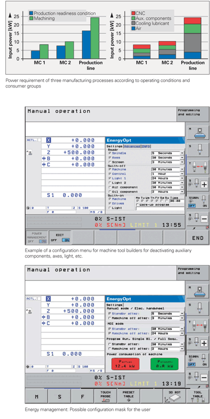
In this example, an aluminum housing with dimensions of 150 mm x 50 mm x 25 mm is to be milled on a machining center with a work envelope of 850 mm x 700 mm x 500 mm. The mean total power consumption of all the above-mentioned consumer groups is 13 kW for roughing and 7.4 kW for fi nishing. The power balance during roughing and finishing provide more detailed information on the distribution of energy consumption among the individual consumer groups.
The cooling lubricant is prepared centrally away from the milling machine (pumping, temperature stabilization). For roughing, this has a mean power requirement of 5.1 kW. For finishing, the mean power requirement decreases to 1.5 kW. Production readiness consumes almost no power. Dry machining offers great potential here for increasing energy and resource efficiency. In many milling applications, however, doing without the cooling lubricant can significantly increase the scrap rate and therefore increase mean energy consumption.
The mean compressed air power changes only slightly in the phases of production readiness, roughing, and finishing. It averages approx. 1.3 kW. Compressed air is required for minimum lubrication of the spindle, tool changing and cleaning the workpiece. In small quantities it is required as sealing air (spindle, tool measurement, linear encoders).
The electrical consumers of the machine include the CNC control with main spindle and feed axis motors as well as numerous auxiliary components (pallet changer, cooling, hydraulics, automation). The power consumption of the auxiliary components varies in the production conditions of readiness, roughing and finishing by only 600 W. With a power consumption of 2.5 kW, the auxiliary components largely determine energy consumption in the production readiness condition. A requirement-oriented deactivation of auxiliary components therefore offers substantial potential energy savings.
The CNC control package with feed axis motors and main spindle require in this example just 27 % of the total power requirement. In both cases, the mean power consumption of the feed motors is 250 W and is largely determined by the holding power of the vertical axis. Short peak values occur only in the accelerating and braking processes.
 Energy efficiency of the drive components
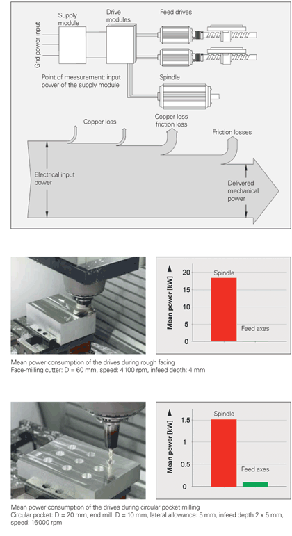
Spindle and feed-axis motors are among the central components of a machine tool. The energy efficiency of a drive component depends on the ratio of delivered power to consumed power and is therefore reflected in the efficiency. The network of drives on a machine tool converts consumed electrical energy to delivered mechanical power. The components of the drive network are a power supply module, drive modules, motors and the mechanical components. Data on efficiency typically refer to the rated power. In other rated values, the efficiency of individual components can vary significantly. HEIDENHAIN supply modules and drive modules attain efficiency values of over 95 %.
Power consumption during milling
Here the power consumption of a main spindle and the feed drives is itemized.
Example 1: Rough facing
During rough facing with paraxial feed rate the feed motors have a mean power consumption of 200 W. The main spindle reaches it rated power at approx. 19 kW.
Example 2: Circular pocket
The circular pocket is machined with a roughing and a finishing cycle. The mean power of the feed drives here is 100 W. The main spindle needs 1.5 kW of power.
Conclusion
Feed drives contribute only a small share of the total power of a CNC and can therefore contribute little to increasing the energy efficiency. On the other hand, the selection of the spindle can have a significant effect on energy consumption. If a spindle drive operates far below its rated power, the intrinsic losses of the drive increase in proportion, with negative effects on the energy balance. If the spindle limits the maximum possible metal removal rate of a milling process, the milling process inevitably takes longer. The result: energy efficiency decreases due to the base load generated by the auxiliary components. There is also potential for more efficient design of milling processes in the consideration of the efficiency of spindle motors, for example by using synchronous instead of asynchronous motors.
 Efficiency of regenerative supply modules
Every acceleration process of a drive requires a braking process in return. The energy from the drives’ moving masses is largely reconverted to electrical energy.
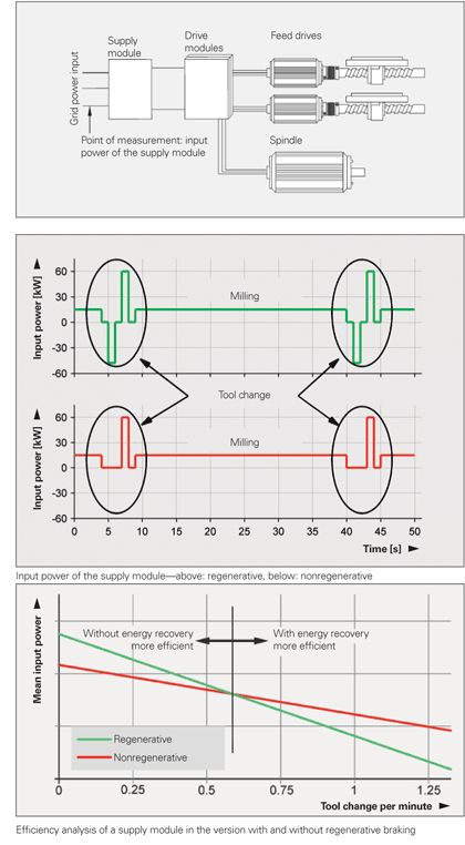
The supply modules of the CNC controls from HEIDENHAIN are designed both for regenerative and nonregenerative braking. In a nonregenerative supply module, the kinetic energy released by the braking process is converted to heat by the braking resistors. A regenerative supply module returns this energy to the power grid. However, the path required for returning the energy and the necessary components for smoothing the grid power generate losses even when the drives have no power requirement. The power loss increases slightly even when power is not being regenerated. A regenerative supply module operates more efficiently than a nonregenerative module when the regenerated energy more than compensates the higher power loss. The decision for a regenerative or a nonregenerative supply module therefore also depends on the expected type of machine operations.
The number of tool changes is important for energy consumption. In one example, a milling operation with 15 kW is interrupted cyclically by a tool change. Starting the spindle requires a peak power of approx. 60 kW. While the regenerative supply module briefl y returns 48 kW to grid power, with the nonregenerative supply module, the kinetic energy is converted to heat.
Due to the high power requirement of metal cutting, the mean input power sinks the more frequently the milling process is interrupted by tool changes. The regenerative supply module works more efficiently as soon as the time interval between two tool changes is less than 100 s (equals 0.6 tool changes per minute). In processes with many tool changes per minute, a regenerative supply module often proves to be the better choice. During contour milling with infrequent tool changes, the advantages are on the side of the nonregenerative system.
 Deactivation of auxiliary components as needed
A comparison of the power consumption of two machining centers (MC) and a production line with three machining stations illustrates again the potential: because the consumption of several consumer groups in the ready condition is only slightly reduced, the nonproductive phases must be kept as brief as possible. With machining centers for smaller production batches, energy consumption can be significantly reduced by the selective deactivation of auxiliary components. Beyond this, potential savings result from the use of energyefficient pumps in the coolant/lubricant circuit.
However, consistent switch-off of auxiliary components (hydraulics, spindle cooling) or the compressed-air supply can also have the opposite effect. If the sudden removal of waste heat from auxiliary components or of the temperature-stabilizing effect of media causes thermal displacement in the machine frame, it can result in scrap parts, which impair the energy balance of a production process. The selective switchoff of auxiliary components therefore functions best on machines with little inclination to thermal displacement. In any case, careful planning of the energy saving effects is a prerequisite.
The CNC can be used as the central control unit for the energy management of a machine tool and its associated periphery. The iTNC 530 is provided with special PLC functions for linking events in the production process (e.g. NC stop) with outputs for controlling auxiliary components. Delay times can be assigned to events so that, for example, motors can be locked and disconnected from current after standstill. Functions for deactivating various auxiliary devices, axes, light in the working space, etc. can be created on this basis. These basic functions can be created as desired by the machine tool builder and adapted to the respective machine model. For the user, a further step is helpful, in which the energy management can be adapted to his specific usage habits. In the illustrated example, the deactivation functions (axis locking, standby, emergency off, switch off) can be configured for various operating modes.
 Reduction of machine idle time through optimal support during setup
Because of the relatively high base energy load of machine tools, non-cutting times have a decisive effect on the energy efficiency of a cutting process. To reduce the energy requirement per part, noncutting periods such as tool and set-up times should be kept as small as possible. In principle, whatever increases the machine’s productivity is efficient.
Non-cutting times during setup
The values in the blocks of NC programs are given with respect to datums on the workpiece that must first be measured on the fixed workpiece. A workpiece touch probe ensures the fast and safe measurement of datums. Predefined touch probe cycles and a delay-free coupling between the touch probe and control considerably reduce non-cutting time and at the same time increase machining accuracy. Datums can be set automatically using the TS touch probes in combination with the probing functions of the TNC controls. This makes it possible to avoid errors during setup that inevitably result in bad parts.
Touch probes can reduce non-cutting time, improve production quality, prevent scrap, and increase productivity. This reduces the energy requirement per manufactured part. The possibilities for reducing non-cutting times are illustrated in these two examples. Here the set-up times are compared with a dial gauge and HEIDENHAIN touch probes on a machine tool with a base load of 4 kW.
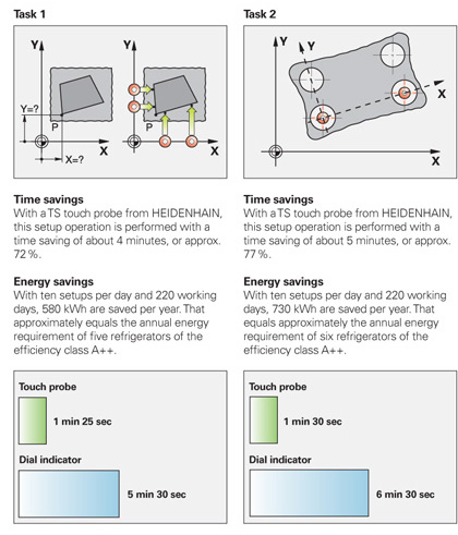
Task 1
- Align the workpiece blank parallel to the axes
- Set the datum in the working plane at a corner
- Set the tool axis datum at the top surface of the blank
Task 2
- Align a workpiece paraxially using two holes
- Set the datum of the working plane in the center of the first hole
- Set the tool axis datum at the top surface of the blank
 Measuring systems for the energy efficient operation of servo-controlled motors
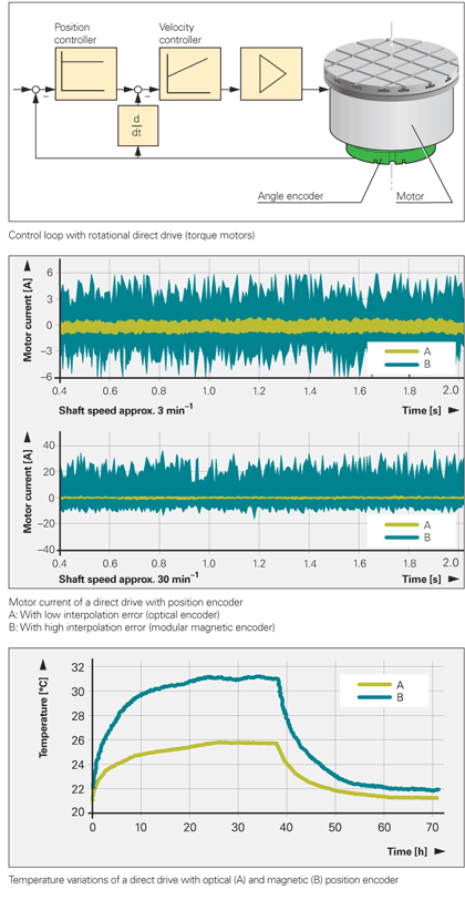
In the control loops of spindle motors and direct-drive feed axes, even the smallest disturbance in the feedback signals can result in large fluctuations in the motor current.
The interpolation of the signal of a position encoder includes short-range deviations within one signal period (interpolation error) typically of approx. 0.5 % of the signal period. If the frequency of the interpolation error increases, the feed drive can no longer follow the error curve. However, additional current components are generated by the interpolation error. Therefore, if the torque remains constant, the energy consumption and efficiency of the motor get worse. The additional energy required is converted to heat. The heat must typically be dissipated by a motor cooling system, which itself consumes energy.
A comparison of the effects of an optical and a modular magnetic encoder on a rotary table with direct drive illustrates the meaning of high-quality position signals. The RCN 226 angle encoder with 16 384 lines generates only barely noticeable disturbances in the motor current, and develops little heat. Because of the magnetic scanning principle, the encoder has notably fewer signal periods. Significant disturbances occur in the motor current with the same controller settings. For example, at a shaft speed of approx. 30 min–1 the effective value of the current is 15 A greater than for an optical encoder. The consequence is greater heat generation in the motor.
An encoder with low signal quality can result in greater energy loss on the motors. In addition, the additional energy requirement of the active cooling has to be included in the energy balance. To increase the energy efficiency of the motor, the encoders should feature high signal quality.
 Minimizing scrap through closed loop technology
Bad parts reduce the productivity of a manufacturing process and therefore greatly contribute to energy costs per manufactured part. A primary cause of the generation of bad parts is the thermal drift of feed axes running on recirculating ball screws.
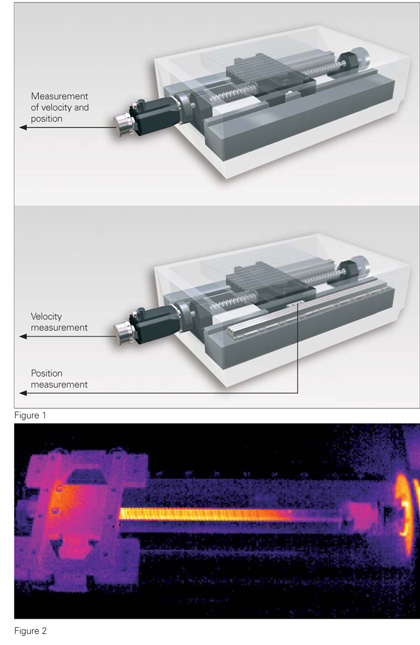
The temperature distribution along ball screws can be changed very rapidly by feed rates and moving forces. On machine tools in a semi-closed loop (i.e. without linear encoders, Figure 1 above) the resulting changes in length (typically: 100 μm/m within 20 min.) can cause significant flaws in the workpiece.
If a linear encoder is used for measurement of the slide position (Figure 1, below), an increase in the ball screw’s temperature (Figure 2) has no infl uence on accuracy. This is referred to as operation in a closed loop because the mechanical errors of the drive are measured in the position control loop and are therefore compensated.
 Example: Machining a coupling lever for an airfoil.
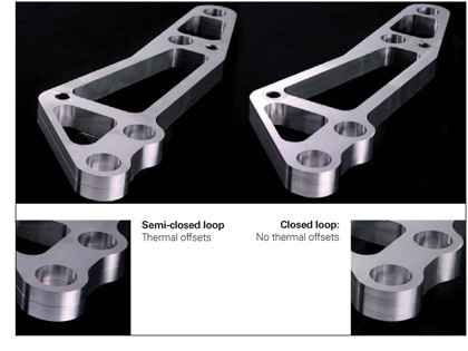
In order to evaluate the accuracy that can be achieved in the manufacture of small batches, a coupling lever is manufactured twice from the same workpiece blank. The second workpiece is simply machined 10 mm below the fi rst. Between the two machining operations, twenty machining cycles for the same part are executed above the blank. In semi-closed-loop operation, the contour of the second workpiece deviates from the contour of the first workpiece, as is shown by an edge. In the semi-closed loop, this offset between the workpieces is 44 μm. With the use of linear encoders in a closed loop, no edge results. A reproducible accuracy from the very fi rst part is thus guaranteed.
 Energy savings in a closed loop
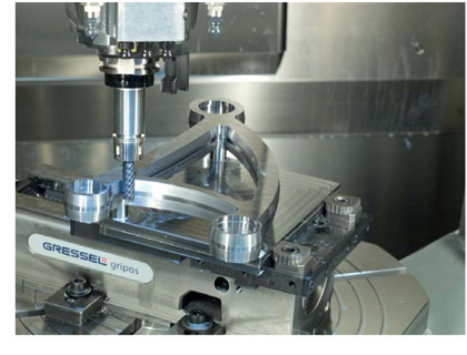
The manufacture of 22 coupling levers in this example takes 2 hours. The bore of two holes at a distance of 350 mm is to be manufactured with the tolerance of IT7, which allows error of ± 28 μm. To manufacture 22 good parts in a semiclosed loop, the machine fi rst has to run the NC program cyclically for 25 min in order to ensure compliance with the IT7 tolerance. During warm-up, the energy consumption is only approx. 10 % below the value for milling.
As a result, the energy costs per good part in the semi-closed loop, are 19 % higher than for manufacturing 22 parts in a close loop with linear encoders. If 50 parts are manufactured on a milling machine in the semi-closed loop with preceding warm-up phase, a power requirement during milling of 8 kW on 220 working days ensues for an additional energy requirement of 660 kWh.
Conclusion
 Analyses of metal-cutting processes show that the power consumption of a CNC control with feed-axis and spindle motors frequently comprise only 25 to 30 % of the total required power. On the other hand, the auxiliary components in the machine or its environment play a dominant role in the energy balance.
There are numerous possibilities for a more efficient use of energy. Significant savings can be realized through the proper selection of components for a machine tool alone. Whether a CNC control should feature energy recovery to line power depends on the frequency of tool changing during milling operations or workpiece changes during turning. The regenerated energy is then available for other consumers in the machine’s environment.
Further energy savings are possible depending on whether spindles can be closely adapted in their speed and torque to the machine’s range of operations. If a universal design of the spindle is required, the spindle motor may have to be run at low efficiency rates—with the expected consequences for energy consumption.
The selection of the position encoder can have a decisive effect on the efficiency of spindle motors and direct drives. Encoders with insufficient resolution and accuracy generate high current values in the position control loop. Position encoders with high line counts are essential for the high efficiency of servo-controlled drives. It has been proven that linear encoders increase accuracy and therefore contribute to higher precision and reproducibility of machining results. This makes it possible to reduce waste in production and, as an immediate result, the energy requirement per good part.
Components for processing cooling lubricants, for supplying compressed air and hydraulics and for cooling occupy a dominant share of the total power. If a machine has particularly efficient pump motors, this alone can save significant amounts of energy. Another opportunity is offered by energy management on the CNC control with selective switch-off of components. This makes it possible, for example, to delay the switch-off of pump drives after a machining operation has ended.
Even in the production process itself, potential energy savings can be found. With the relatively high base load of machine tools, a reduction of nonproductive phases is a high priority. Here the CNC controls from HEIDENHAIN can help in many ways. Beginning with ideas for user-friendly program editing to functions for workpiece setup with HEIDENHAIN touch probe systems, all the way to more efficient and exact motion control in three and fi ve-axis machining, users profi t from the know-how collected by HEIDENHAIN in decades of experience in metal-cutting technology.

