March 28, 2016
Accuracy and safety significantly improved
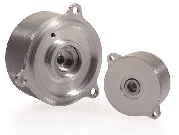
FIGURE 1: Outstandingly well suited for highly dynamic, energy-efficient servo drives: the ECI/EQI 1100 inductive rotary encoders with 37 mm diameter (at right) and ECI/EQI 1300 with 65 mm diameter (at left)
 Whether small, large, singleturn or multiturn, whether with or without integral bearing: the rotary encoder program from HEIDENHAIN offers the right solution for any task. Of particular interest are the current series of inductive rotary encoders ECI/EQI 1100 and ECI/EQI 1300.
With respect to their predecessors, the ECI/EQI 1100 and ECI/EQI 1300 inductive rotary encoders without bearings (Figure 1) offer distinctly improved control quality and system accuracy. Also, they are strongly resistant to vibration. They are available in typical sizes with diameters of 37 mm (ECI/EQI 1100) and 65 mm (ECI/EQI 1300). HEIDENHAIN was able to realize them thanks to a newly developed ASIC.
All variants support the safety integrity level SIL 2, Category 3 PL d. Additional measures in the control can enable attainment of even SIL 3, category 4 PL e. The mechanical fault exclusion, which prevents loosening of the shaft or stator connection, is an additional benefit. With this performance and feature level, they are excellently suitable for position acquisition on highly dynamic, energy-efficient servo drives for safety-related applications.
Impressive results from a comparative test
The modern inductive rotary encoders have no reason at all to hide from comparisons behind their counterpart with optical scanning. The encoders with optical scanning do remain the first choice for the high end of the application spectrum. However, in terms of control quality, dynamics and position error, the new inductive solutions from HEIDENHAIN have gained significant ground, and in terms of durability they are even superior.
This is shown in comparative tests between the new generation of inductive rotary encoders, their predecessor models, and optical rotary encoders using a real motor. To keep possible influences of the motor to a minimum, a model was chosen with extremely low cogging torque for the measurements. A high-precision angle encoder was mounted on the output shaft of the motor (measuring accuracy of better than ± 1 angular second) to assess the drive system with regard to accuracy and rotational speed behavior.
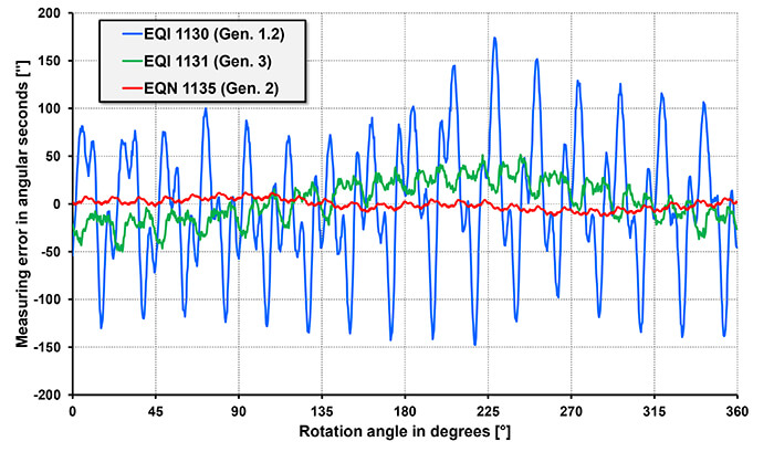
FIGURE 2: Typical accuracy curves of inductive and optical rotary encoders over one revolution (using the EQI 1100 with 37 mm diameter as example)
Accurate and dynamic
The system accuracy is a critical criterion for assessing suitability for specific applications. Figure 2 shows the recorded accuracy curve in a comparison of multiturn rotary encoders with diameters of 37 mm. Compared with the previous model, the new EQI 1131 inductive rotary encoder has greatly reduced short-range measurement errors. As expected, the EQN 1135 optically scanned encoder offers the highest accuracy. The accuracy curves are comparable for the larger rotary encoders with 65° diameter.
The examination of dynamic behavior in the control loop shows that the attainable dynamics depend only on the adjusted controller parameters. The large bandwidth that can be achieved with HEIDENHAIN rotary encoders enables you to realize systems with greater performance. Here it is the complex control paths that limit the achievable dynamics of the whole system, not the encoders.
Very good speed stability
On a high-end servo motor, however, the encoder’s influence plays a decisive role for speed stability. Figure 3 shows the speed stability of a controlled motor at different speeds. As was already the case in the comparative test for system accuracy, multiturn rotary encoders with 37 mm diameter provide the control loop feedback. And as with the system accuracy, these results can also be transferred to the larger variants. Speed stability with the new inductive rotary encoders differs only slightly from that of optical devices. Thanks to their robust scanning and higher tolerance to vibration (stator: ≤400 m/s², rotor: ≤600 m/s²), they are ideal for production machines.
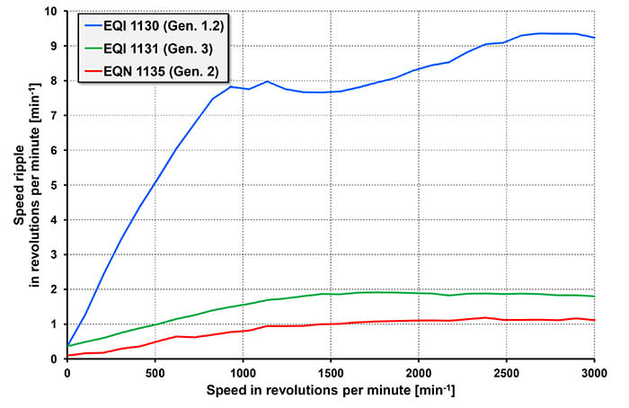
FIGURE 3: Speed stability of motors with inductive and optical rotary encoders (using the EQI 1100 with 37 mm diameter as example)
Mechanically and electrically compatible
The new ECI/EQI 1100 and ECI/EQI 1300 inductive rotary encoders are compatible in their mounting dimensions with the optically scanned rotary encoders with integral bearing of the ECN/EQN 1100 and ECN/EQN 1300 series. The mechanical and electrical compatibility achieved this way make it possible to select from the HEIDENHAIN program the best suited rotary encoder for the specific control requirements of the application and minimize the number of motor variants.
In the current series, compared with the previous generation, the permissible mechanical tolerance in particular has been greatly extended, for example by a factor of 2 for the permissible axial motion. For simple verification of the mechanical mounting, the encoders generate a value for the mating dimension, which the servo inverter reads out via the EnDat interface. The new inductive rotary encoders also support monitoring of the encoder temperature and motor temperature. An integrated temperature sensor monitors the encoder temperature and an external temperature sensor can check the motor temperature. Without interrupting the control cycle, the rotary encoders evaluate data from the two sensors and the subsequent electronics can read out the data digitally via the EnDat 2.2 interface.