
 Print
Print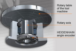
5-Axis Machining: Getting a Grip on the Accuracy of Rotary Axes
Understanding challenges to accuracy and being able to judge measurement concepts help in gaining an insight into measuring technology and machine tools. That can be important, for example, when selecting a suitable machine tool for your own applications, especially if production quality has a high priority. In this article, we are placing emphasis on the accuracy of rotary axes.
In contrast to conventional 3-axis machines, 5-axis machining has completely new demands in terms of axis accuracy. It is not only a question of the precision of individual axes here, but of their accuracy in the working space. As a result, however, the number of error sources is significantly increased by the higher number of mechanical components in the machine design. Depending on the specific machine design, angle measurement is of particular importance here.
What sources of error exist?
The many mechanical components of a machine are all possible sources of errors. These are all stressed by the enormous dynamics of the working processes. Typical causes for inaccuracies are:
- Wear caused by high mechanical loads, for example, or collisions during machining
- Elasticities in transfer elements, e.g., the worm shaft, or instabilities of the bearings
- Geometric errors e.g. radial eccentricity of mechanical transfer elements or incorrectly installed components
How can sources of error be avoided or reduced?
During the design of a machine, sources of error in connection with the rotary axes should be ruled out as far as possible. As a part of the kinematic influences, different mechanical and control-oriented designs of rotary axes should be compared.
Rotary axes feature complex mechanics with various components subjected to possible sources of error. Optimal compensation would have as a prerequisite the recognition of all possible error sources for every situation. And exactly that is not possible.
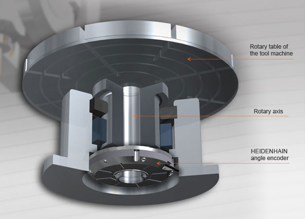
A possibility for getting a grip on position deviations of rotary axes is the use of a suitable HEIDENHAIN angle encoder. For better understanding of the effect, here are two basic strategies for the design of rotary axes in control loops:
—“Semi-Closed Loop”
If the position of the rotary axis is measured solely via the rotary encoder on the motor, then we refer to a “semi-closed loop”. Not only is the lack of accuracy of the motor encoder significant with this arrangement, but many other errors also play a part such as wear, elasticity deviations and geometric errors of the mechanical transfer elements.
—“Closed Loop”
If an angle encoder mounted directly on the rotary axis is used for position measurement, most sources of error can be avoided. This method is known as the “closed loop” method. Use of an angle encoder with integral bearing is recommended in this respect so that the previously described elasticity deviations do not lead to additional angle deviation. When using an angle encoder with integral bearing, it is presumed that the minimal angle error of an axis lies within the system accuracy of the angle encoder (the accuracy of an angle encoder of ± 2’’ corresponds to a deviation of ± 5 μm for a table diameter of 1 m).
Of course spatial deviations also accumulate due to elasticity of the axes. Angle encoders with integral bearing and a hollow shaft have an additional advantage: an integrated coupling that compensates for shifts of the axis midpoints without additional angle errors. On the other hand, angle encoders without integral bearing would lead to eccentric deviations and would therefore provoke additional angle errors.
Are direct drives a positive trend?
With respect to accuracy, direct drives have several advantages and hardly any disadvantages. In the mid-term, an extensive transition from mechanical transfer elements with servo motors to direct drives (torque motors) can be expected. The decisive advantage is the very stiff coupling of the drive to the feed component without any other mechanical transfer elements. This is of true significance for a high level of contour constancy and optimal surface quality.
With the use of direct drives, an additional rotary encoder for speed definition is required. Position and shaft speed are defined by the angle encoder mounted directly to the rotary axis: a “closed loop”. Since there is no mechanical transmission between the speed encoder and the feed unit, the angle encoder must have a correspondingly high resolution and signal quality in order to allow exact speed control, particularly at slow speeds.
Conclusion
System errors can be avoided with the selection of suitable measuring technology. That applies in particular to rotary axes. Because of their complexity, accuracy is a major challenge.
Especially with interpolated 5-axis machining and direct drive technology, encoders that do not convert unavoidable spatial deviations into large-scale angle errors are recommended.
This challenge can be mastered with angle encoders (with integral bearing, integrated coupling and absolute position measurement) directly mounted on the rotary axis (such as the RCN model).
The best solution is angle encoders with integral bearing, integrated coupling and absolute position measurement, directly mounted to the rotary axis.
Angle encoders
The term angle encoder is typically used to describe encoders that have an accuracy better than ± 5". In contrast, rotary encoders are encoders that typically have an accuracy worse than ± 12". Angle encoders are found in applications requiring precision angular measurement to accuracy within several arc seconds. These include rotary tables and swivel heads on machine tools, C axes of lathes, measuring machines for gears, printing units of printing machines, spectrometers, telescopes, etc.
The following mechanical design principles can be defined:
- Angle encoders with integral bearing, hollow shaft and integrated stator coupling
- Angle encoders with integral bearing for separate shaft coupling
- Angle encoders without integral bearing
For comparison: Accuracy of linear axes
As with angle encoders, linear encoders can also significantly increase the accuracy of feed axes. And here as well – as is often the case with HEIDENHAIN – many influences are rendered unimportant by the design: If a linear encoder is used for measurement of the slide position, the position control loop covers the complete feed component. Play and inaccuracies in the transfer elements of the machine have no influence in this case on the accuracy of the position measurement. Measurement accuracy really only depends upon the precision and installation location of the linear encoder.
Additional Resources