July 31, 2015
Inductive multiturn rotary encoders with improved control quality
Compact, durable and safe in applications up to SIL 3
Users of machine tools, robots and general automation technology are constantly demanding solutions that are high in performance and low in cost. The response to this are dynamic,
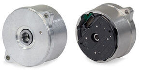
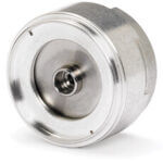
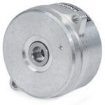
Figure 1: ECI 1119 / EQI 1131 FS – inductive rotary encoders with a diameter of 37 mm
compact and energy-efficient drives with safety functions. Due to the differing requirements of the individual applications, functionally safe encoders are needed both for the high-end range of machine tool drives as well as for standard applications. With the series launch of the third generation of bearingless rotary encoders of the ECI/EQI 1100 series with inductive scanning and a size of 37 mm, HEIDENHAIN is offering its portfolio of highly dynamic and energy-efficient servo drives for safety-related applications.
With its newly developed ASIC, HEIDENHAIN has produced a functionally safe solution with an inductive rotary encoder for the 37mm range. The encoder supports the safety integrity level SIL 2, Category 3 PL d. Additional measures in the control can enable attainment of even SIL 3, category 4 PL e. Another advantage is the mechanical fault exclusion, which prevents loosening of the shaft and stator coupling.
Moreover, the system accuracy in comparison with previous generations was improved by more than twice to ± 120 angular seconds. Thanks to its contamination tolerant inductive scanning principle, these encoders are characterized by high durability. The new inductive rotary encoders ECI 1119 FS (singleturn) and EQI 1131 FS (multiturn) are also compatible with the optically scanned rotary encoders with integral bearing of the ECN/EQN 11xx FS series. The mechanical and electrical compatibility made possible with this design ensures scalability according to the control requirements of the application, and the number of motor variants can be minimized.
Compared with the previous generation, in particular the permissible mechanical tolerance has been greatly extended, for example by a factor of 2 for the permissible axial motion. For simple verification of the mechanical mounting the encoder generates a value for the mating dimensions, which the servo inverter reads out via the EnDat interface. The new inductive rotary encoders also support monitoring of the encoder temperature and motor temperature by an integrated temperature sensor and external temperature sensor respectively. The rotary encoder evaluates the data from the two sensors and without interrupting the control cycle the subsequent electronics can read out the data digitally via the EnDat 2.2 interface.
Control quality compared with optically scanned encoders
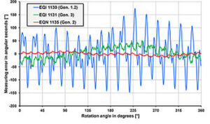
Figure 2: Typical accuracy readings of inductive and optically scanned rotary encoders for one revolution
In the following, we take the example of a real motor to compare the new generation of inductive rotary encoders with its predecessors and an EQN 1135 optically scanned encoder. To keep possible influences of the motor to a minimum we have chosen a model with extremely low cogging torque for the measurements. A high-precision angle encoder was mounted on the output shaft of the motor (measuring accuracy of better than ± 1 angular second) to assess the drive system with regard to accuracy and rotational speed stability.
System accuracy
The system accuracy is a critical criterion for assessing suitability for specific applications. Figure 2 shows the recorded accuracy of the three encoders. Compared with the EQI 1130, the new EQI 1131 inductive rotary encoder has greatly reduced short-range measurement errors. As expected, the EQN 1135 optically scanned encoder produced the highest accuracy results.
Dynamic behavior in the control loop
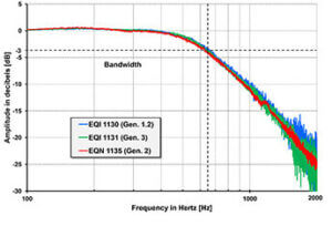
Figure 3: Frequency response of inductive and optically scanned rotary encoders in the closed speed control loop.
The investigations of the dynamic behavior in the control loop were made with a cascading control structure of the motor currents, the speed and the position. To achieve a good level of comparability the control parameters were set identically for all the encoders investigated (control cycle time 100 µs, proportionality gain of the speed controller 1400 1/s). Figure 3 shows the amplitude frequency response of the closed speed control loop for the three encoders (Bode plot). The drive system achieved a control bandwidth of approx. 600 Hz with all three encoders. No points of resonance were detected. The achievable dynamics depends only on the controller parameters set. The large bandwidth that can be achieved with HEIDENHAIN rotary encoders enables you to realize systems with greater performance in which it is not the encoders that limit the achievable dynamics of the whole system, but the complex control paths.
The high setting of the speed controller gain ensures that the mechanical interference on the motor shaft is well suppressed. However, this also significantly amplifies the rotary encoder’s measurement errors. Thus, in the case of high-performance servo motors, it is the influence of the encoder and not the mechanical influences of the motor (cogging torque, for example) that plays the decisive role for speed stability. Figure 4 shows the speed stability of the controlled motor at different speeds. The speed stability of the new inductive rotary encoder is only slightly different from that of the optical device. Therefore, thanks to its tolerant scanning and higher vibration resistance (stator: ≤ 400 m/s², rotor: ≤ 600 m/s²), the new inductive rotary encoder is optimally suitable for production machines. The significantly reduced speed ripple in the new inductive encoder is primarily due to the reduction of short-range position errors.
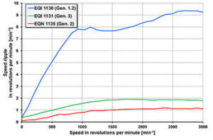
Figure 4: Speed stability of motors with inductive and optically scanned rotary encoders
Limited resolution manifests itself in drives as quantization noise of the measured speed. The quantization noise plays a role mainly at high frequencies because the derivative of the (quantized) position is required for the speed. This high-frequency noise is coupled into the current control loop by the speed control loop. The current noise leads to forces and torques in the motor, which can trigger natural mechanical frequencies and also become apparent as noise emission. Furthermore, this causes higher losses in the motor, which have a negative effect on the energy performance. Therefore, high position resolution is a must for highly dynamic drives.
Position error in the position control loop
Depending on the task, the accuracy and/or reproducibility of the rotary encoder is relevant for the positioning accuracy. The reason for the position error around the nominal position lies in the noise sources of the drive system and in the quantization of the quantities to be measured (position, speed and current). If a position is to be approached as fast possible, this requires high loop gains in the speed controller and position controller. However, this means that also the errors of the actual value acquisition are coupled into the control loop. In order to achieve the best possible performance in positioning mode, once again encoders with the highest possible signal quality are required, as provided by HEIDENHAIN.
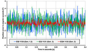
Figure 5: Position noise in position control mode with inductive and optically scanned rotary encoders
The noise of the encoder signal plays a role when holding a specific position of the motor shaft. Both the noise that is always present in the encoder already before the position is digitized and the quantization noise from the finite position resolution cause actual value deviations in the control loop. The closed-loop control attempts to compensate these deviations by setting torques that cause small movements in the motor around the desired position. These movements are shown in Figure 5. As expected, the optically scanned encoder gets top marks thanks to the highest effective resolution.
Need help choosing a rotary encoder for an automation project? Use our selector tool to narrow your search fast.
Summary and outlook
The newly developed inductive multiturn rotary encoders ExI 11xx of the 3rd generation enable you to implement functionally safe systems up to SIL 3 with one measuring device. The mechanical (mounting) and electrical (EnDat 2.2 interface) compatibility with the ExN 11xx optically scanned rotary encoders means that practically the entire spectrum of applications can be served. All users, however, can benefit from very good control characteristics with regard to high accuracy, dynamic performance, efficiency, rugged design, compactness and generous mounting tolerances.
 EQI 1130 Generation 1.2
- EnDat 2.1 (18-bit singleturn, 12-bit multiturn), ≤ 2 MHz clock
- No analog signals (purely serial)
- Without integral bearing
- Without support for temperature evaluation
- System accuracy ±280”
- Permissible axial motion of the drive shaft ±0.2 mm
- Vibration resistance in compliance with EN 60068-2-6:
Stator ≤ 300 m/s²
Rotor ≤ 300 m/s²
For applications with moderate requirements for control quality and accuracy
EQI 1131 Generation 3
- EnDat 2.2 (19-bit singleturn, 12-bit multiturn), ≤ 16 MHz clock
- No analog signals (purely serial)
- Without integral bearing
- Evaluation of an integral and an external temperature sensor
- System accuracy ±120”
- Permissible axial motion of the drive shaft ±0.4 mm
- Vibration resistance in compliance with EN 60068-2-6:
Stator ≤ 400 m/s²
Rotor ≤ 600 m/s²
Optimum for modern production machines with functional safety
 EQN 1135 Generation 2
- EnDat 2.2 (23-bit singleturn, 12-bit multiturn), ≤ 8 MHz clock
- No analog signals (purely serial)
- with integral bearing
- Evaluation of an integral and an external temperature sensor
- System accuracy ±60”
- Permissible axial motion of the drive shaft ±0.5 mm
- Vibration resistance in compliance with EN 60068-2-6: ≤ 300 m/s²
For high-end drives for machine tools with functional safety, for example