March 28, 2016
Greater margins for tolerances
 Large-batch production in the automotive industry is in the midst of a change. For example, inflexible transfer lines are increasingly being replaced by lines with chained machining centers so as to improve flexibility in the mechanical machining of vehicle powertrain components. HEIDENHAIN linear encoders in a Closed Loop configuration help increase machining accuracy. This affords margins in the tolerance budget for other errors.
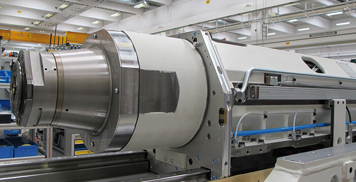
Horizontal machining center with HEIDENHAIN linear encoder (photo: GROB-WERKE GmbH & Co. KG)
The purchasing behavior of car drivers has distinctly changed over the past years. They want ever more versions of models and engines and at the same time vehicles with increasingly greater efficiency. The automobile manufacturers react with more frequent model changes and more engine versions. For their large-batch production this means shorter product cycles, greater diversity and smaller batches, all of which translates into greater all-round flexibility.
Flexibility through linked machining centers
Automobile manufacturers boost flexibility by switching to production with linked machining centers (Figure 1). Machining centers permit faster reaction to fluctuations and changes in demand, the machining of different versions of a workpiece without retooling on the same production line (version flexibility), and the adding or removing of machines relatively easily to and from the production line (re-use flexibility).
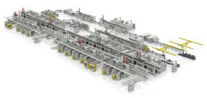
Figure 1: Representation of a modern production line with linked machining centers (photo: MAG IAS GmbH)
The produced tolerances of a workpiece depend on the individual machines or sub-processes of the complete production system. The aim, therefore, is to reliably maintain workpiece tolerances throughout the entire process. Each single machining center should only use up as little as possible of the available tolerances. Then, the greater the remaining tolerance reserve, the greater the margin automobile manufacturers have to compensate process influences that are hard to control, and to optimize the accuracy of their components.
Tolerances in a class of their own
Compared with the demands in other areas of production like tool and mold making, for example, the tolerances in large-batch production seem quite large. However, the required tolerances have to be maintained over a long period of time and for large numbers of workpieces at a defined level of reliability. To ensure this the automobile manufacturers perform statistical capability tests with the machining centers.
The following example demonstrates the effect of these capability tests: a hole in the bearings of a gearbox, for example, has a specified tolerance of ±0.1 mm in depth. In order to reliably maintain the required specified tolerance in production there is a further restriction of the tolerance through so-called capability values. This restriction means that the actual finished depth tolerance of the hole has to be in the range of ±0.06 mm for a large number of finished parts.
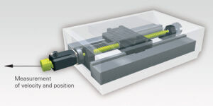
Figure 2: Position measurement in Semi-Closed Loop mode
This tolerance is now shared by different potential errors of the machine tool and the process chain including workpiece clamping, tool clamping, thermal axial drift on the ball screw, thermal expansion of the ball screw on the feed axes and many more. Furthermore, there should be a tolerance reserve left permitting the machines and process to compensate unforeseeable influences on production which are difficult to control.
Position measurement on feed axes with ball screw
The position of an NC feed axis can be measured in principle through the ball screw in combination with a rotary encoder (Semi-Closed Loop, Figure 2), or through a linear encoder (Closed Loop, Figure 3). Semi-Closed Loop means the position control loop of the feed axis is closed via the encoder of the feed motor. The position of the axis slide is identified here by the pitch of the ball-screw drive in conjunction with the rotary encoder. However, thermal expansion and wear of the ball screw are not included as factors in the position measurement. You could say that the Semi-Closed Loop control is blind to such alterations of the machine tool’s mechanics.
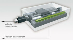
Figure 3: Position measurement in Closed Loop mode
It is therefore recommended also for large-batch production with linked machining centers to implement machine tools with closed-loop control. In this case the position of the feed axis slide is measured with a linear encoder and fed back into the axis control as actual position value. In this way the thermal expansion of the ball screw is determined directly on the axis slide and compensated accordingly.
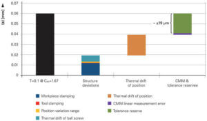
Figure 4: Composition of the evaluated error limits on a machining center with Semi-Closed Loop control; thermal expansion of the ball screw takes the major share.
Closed Loop: determining thermal expansion
Evaluations of the error limits show that one of the biggest consumers of the available tolerance in the machining center is the uncontrolled thermal axial expansion of the ball screw when using Semi-Closed Loop position measurement. Figure 4 (left) shows the distribution resulting from examinations of the composition of error limits based on the example described above of a hole with a restricted tolerance of ±0.06 mm.
The error limits of this machining example show that a Closed Loop control practically eliminates the influence of thermal expansion and wear of the ball screw (Figure 5). In our machining example this increases the tolerance reserve by 20 µm to 39 µm. This makes about two thirds of the tolerance available to compensate unforeseeable influences in the production chain which are difficult to control, like fluctuations in the shop, coolant and workpiece temperatures, for example.
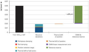
Figure 5: In the Closed Loop the thermal expansion of the ball screw no longer plays a major roll. The tolerance reserve increases to over half the tolerance.
Actively using the tolerance reserve
To meet future demands for reduced exhaust emissions and fuel consumption, design will have to reckon with higher part accuracy—in other words tighter workpiece tolerances and more stringent surface quality values. The reason is that this will decrease friction in the vehicle’s powertrain and therefore deliver the desired reductions. The tolerance reserve from the Closed-Loop control thus provides the margin for large-batch production to implement the even tighter design tolerances to be expected in the future.
The increased tolerance reserve no longer has to be kept exclusively as a safety net for all eventualities. It can now be actively used to boost productivity and quality. For example, it would be possible to expend part of the tolerance reserve for tool wear. For the machining of workpieces of cast iron (e.g. crankcases) or high-temperature resistant cast steel (e.g. exhaust gas turbochargers) with high levels of tool wear, such raising of the wear limit leads to significant savings and increased productivity. Among other things, this is due to longer tool life, reduced testing and compensation, and longer machine runtimes. Therefore, using linear encoders in the feed axes of machining centers contributes to reducing production costs.