June 27, 2010
Early warning system for production systems
Often it is small modules in production systems, such as rotary encoders, which make it necessary to shutdown the plant for their replacement in case of faults, thus resulting in enormous costs, which are out of all proportion to their actual price. This can be avoided by the use of rotary encoders which are capable of self diagnosis and can indicate internal problems so that maintenance can be planned as early as possible.
If small modules in a plant or machinery break down without notice, the costs for the replacement part are usually out of all proportion to the damage caused by the interruption of production. For example, in the paper industry the costs of each hour of interrupted production are on the order of $7000 and more. As rotary encoders are among the key components of modern machinery and plant control units, it makes sense to equip these components with a diagnostic system which continuously monitors the internal functionality of the rotary encoder and therefore provides a basis for initiating maintenance measures in good time.
The rotary encoders used in today’s production plant are often subjected to high mechanical stresses in the form of shock and vibrations as well as high temperatures. The following typical component specifications reflect these stresses: Vibration-resistance up to 100 m/s2, shock resistance up to 1,000 m/s2, axial load 100 N and radial load up to 300 N. Under these general conditions a positioning accuracy of 0.1 mm must still be ensured.
Typical Causes of Failure of Rotary Encoders
It is therefore no wonder that rotary encoders break down in spite of their being very robust. The following are some of the “typical” reasons for the breakdown of rotary encoders.
- Worn-out ball bearings due to poor installation:
The connection of the rotary encoder to the motor shaft can be made by means of a coupling (typical for shaft encoders) or by plugging onto the shaft (typical for hollow shaft encoders), whereby the rotary encoder is prevented from rotating by means of a torque support. If the specified minimum tolerances are not complied with, imbalance results, which causes premature wear to the ball bearings. The result: a wobbling of the increment-disc. Individual areas lose contrast, which in turn causes the loss of several pulses. Specifically this means: The rotary encoder still functions, but the entire drive unit becomes irregular as the frequency inverter attempts to compensate for these fluctuations. - The “loose contact”:
Imbalance of the drive unit may put excessive strain on soldered joints and (terminal) contacts, so that bad contacting causes sporadic faults. - Soiling in the rotary encoder causes dust particles to be deposited on the increment disc:
When dust particles are present on the incremental disc, suddenly the rotary encoder then detects two increment lines as one, and therefore produces one pulse too few. This can happen for example with assembly under difficult conditions with high levels of dust if the connection cover is opened. (In such cases it is advisable to use versions with external plug connections.) - Moisture in the connector or in the housing:
If, for example, cables are used which are too thin, moisture can penetrate into the rotary encoder through the cable gland and cause sporadic malfunctions - Overheating:
As the rotary encoders are often installed behind a fan, the exhaust air from the motor is passed over the encoder. If a motor bearing is faulty, the hot exhaust air from the motor can cause the failure of the rotary encoder.
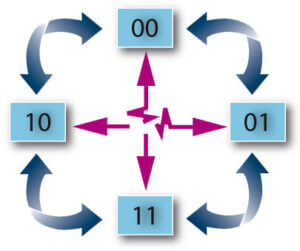
Fig. 1: By means of the “Advanced Diagnostic System” each counter difference is recognized regardless of the direction of rotation. If the correct pulse sequence (green arrows) is interrupted (red arrows), an error message is given.
Fig. 2: According to the type of fault, the error message is made on the basis of various signal sequences, which are output via a potential-free optocoupler.
A fault with many installations is also the fact that monitoring of the rotary encoder is only implemented in the frequency inverter. However, between the inverter and the rotary encoder there are enough cables and terminals to cause problems. For example, a crushed cable can lead to an interruption of the signal, which is mistakenly interpreted as an encoder fault by the inverter and results in the user exchanging a component, without the actual fault being remedied.
In order to avoid such false diagnoses and sudden failures of rotary encoders – and rather to “announce” these in advance, Leine & Linde(a HEIDENHAIN Corporation sister company) has integrated a unique early warning system into its rotary encoders. CalledAdvanced Diagnostic System” (ADS™), this system for automatic self-diagnosis works as follows:
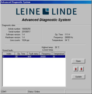
The evaluation software provides the user with an overview of the type of rotary encoder problem, the time of the fault and the condition and encoder data.
Integrated Early Warning System
For example, the rotary encoder internally monitors the completeness of the pulses and the correct pulse sequence (Fig. 1). Even a single counter difference from the programmed division is registered by the system and reported via a potential-free switching output (Fig. 2); this can, for example, be evaluated and displayed by an overriding system control system. For this an additional wire is necessary. In parallel to the switching output, the fault is indicated by a flashing LED on the rear of the housing. In case of upgrading, this enables the ADS™ to be used without additional wiring. Often, rotary encoders are installed in visible positions, so that a sporadic visual check by the user is sufficient. The flashing LED can be easily seen at a distance of 10 m.
As part of ADS™, Leine and Linde stores the time of the fault and the corresponding error code in the rotary encoder so that the user has the opportunity to read out and analyze the error code via an RS-232 interface (once the encoder has been removed). For statistical purposes the number of operating hours, the speed of rotation and the current temperature are also measured in the encoder. In addition, the highest and lowest temperature is stored. There is also a differentiation between individually occurring errors and continuous problems.