A New Dimension in the Nanometer Range
 The trend in the semiconductor industry to ever higher levels of integration and, with it, to continuously finer structures, calls for measuring devices with high resolution for positioning to the nanometer in the manufacturing process and in measuring and inspection technology. Measuring error due to guideway influences and thermal expansion, which at present cannot be compensated by computation, can be ascertained by a new measuring device and therefore significantly reduced. “To purposefully change something, you must first be able to measure it.” Source: “Crash Course in Nanotechnology,” keynote speech by Dr. Alois Rhiel, February 2006.
Encoders with high resolution
The concept of nanotechnology is used for a number of technologies that involve structures and processes in the nanometer range, and it is considered a key technology of the 21st century. A nanometer is a billionth of a meter (10-9 m) and denotes a limit range in which quantum physical effects begin to play an important role. Nanotechnologies such as those seen in optical and semiconductor manufacturing use machines as well as measuring and testing equipment with high positioning accuracy and repeatability. The specified values lie in the range of 100 nm to 1 nm and even smaller.
The encoders in these machines are subject to very stringent requirements for signal quality and accuracy. These requirements are met by laser interferometers or interferential optical encoders as position measuring devices. Both already offer very high resolutions well below 1 nm. Laser interferometers can be simply aligned with the tool center in order to eliminate Abbe error. One of the most serious disadvantages of these devices, however, is their dependency of the wavelength of laser light on environmental parameters such as temperature and air pressure. These have to be carefully measured along the interferometer’s optical path and the error must be continuously compensated. Any fluctuation, be it ever so small, of temperature, air pressure, the composition of air and similar parameters ultimately results in a change in the wavelength of light and leads over a measuring length of 500 mm to position fluctuations in the order of 50 nm. The alignment error of the laser, which changes over time, lead to cosine or Abbe error that has to be calibrated continuously.
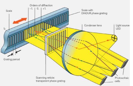
Figure 2: Interferential measuring principle
Stable measuring standards normally have a defined thermal behavior and are independent of air pressure fluctuations. In recent years, the LIP, LIF and PP product families from HEIDENHAIN have established themselves as stable measuring standards. The interferential scanning principle behind them exploits the diffraction and interference of light on a fine graduation to produce signals used to measure displacement that are therefore insensitive to air fluctuations. A relative motion of the scanning reticle to the scale causes the diffracted wave fronts to undergo a phase shift: when the grating moves by one period, the wave front of the first order is displaced by one wavelength in the positive direction, and the wavelength of diffraction order –1 is displaced by one wavelength in the negative direction. Since the two waves interfere with each other when exiting the grating, the waves are shifted relative to each other by two wavelengths. This arrangement results in two signal periods from the relative motion of just one grating period. Interferential encoders function with grating periods of, for example, 8 µm, 4 µm and finer. Their scanning signals are largely free of harmonics and can be highly interpolated. These encoders are therefore especially suited for high resolution and high accuracy and a very high inherent repeatability. Even so, their generous mounting tolerances permit installation in a wide range of applications.
Influence of guiding error
 All linear bearings have angular guiding error (pitch, yaw and roll) and linear guiding error (straightness, flatness). The error typically lies in the range of 5 to 100 µrad or 0.5 to 5 µm. The relevant statistical dispersion of this error is only a fraction of these values and is very small for air bearings. Angular guiding error leads to local tilting and, with an Abbe offset other than zero, to a length offset of the encoder and thereby influences the machine accuracy.
Temperature as “spoilsport”
Although increasing temperature within a certain range improves people’s wellbeing, temperature fluctuations are true spoilsports for measuring and testing technology in regard to accuracy and reproducibility.
Under temperature fluctuation, the accuracy of the system remains limited in spite of expensive designs and materials or additional measures (such as active cooling). Thermally induced geometrical changes of the machine can be mathematically compensated, if only with limitations. The value of temperature measurement via sensor for linear compensation of thermally induced expansion depends upon – the quality of the sensors used – the correct placement (e.g. with inhomogeneous temperature distribution) – the aging of the sensors, and – in addition, calibrated temperature sensors must be continuously monitored and, if required, replaced with sensors with the same properties. Linear motors are also heat sources, especially on fast machines, and can cause thermomechanical deviations. Because of their complex designs, gantry axes require special examination in this regard. The influence of guiding error and thermal changes presents great challenges on the road to nanometerexact positioning within manufacturing processes and in measurement and testing metrology. A new type of measuring device from HEIDENHAIN can contribute to meeting them.
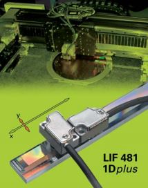
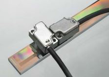
LIF 481 1Dplus Encoder
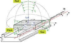
Figure 4: LIF 481 1Dplus, a new type of encoder with x axis and additional y axis
Decades of experience in the field of microstructuring, together with corresponding equipment for scale carrier manufacture and modern structuring and production machines, similar to those found in semiconductor manufacturing, have combined to fulfill the market demand for a quasi two-dimensional measuring device.
Besides the usual longitudinal track (x axis) with the interferential graduation of the familiar LIF (4 µm signal period), the LIF 481 1Dplus features an additional y axis track perpendicular to it. This nevertheless does not require eliminating of the reference mark on the longitudinal track. As is usual at HEIDENHAIN, the absolute position on the scale, established by the reference mark, is gated with exactly one measuring step
The glass ceramic ZERODUR® is used in a graduation carrier whose expansion coefficient of 0+/- 0.1 x 10⁻⁶ K-1 is exact over a large temperature range and is characterized by high resistance to aging. With the appropriate arrangement of two or three scanning heads (Figure 5) the LIF 481 1Dplus linear encoder makes it possible to measure and compensate linear and angular guiding error or the in uences of thermal expansion:
Recording the “real-time condition” and compensation of the actual measured values contribute significantly to the improvement of positioning accuracy in the nanometer range. These ambitious expectations of the encoder were confirmed with the impressive results of an experiment.
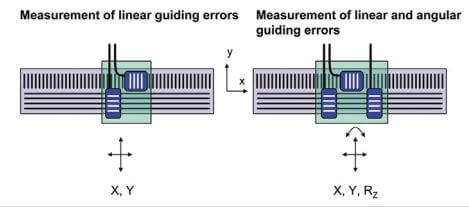
Figure 5: Arrangement with 2 or 3 scanning heads
 Test setup
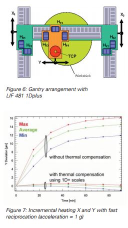
Figure 6 shows an example of the user of 1Dplus scales on a gantry-type milling machine. The x axis is equipped with two heads HX1, HX2 in an example arrangement of the scales. If the tool center point (TCP) is also aligned in Z to the centers of rotation HX1 and HX2, all Abbe offsets of the X axis are equal to zero. The heads HY1 and HY2 detect straightness error (y) of the X guideway axis and, to an extent, the in uences of thermal expansion. On the Y axis the heads HX3 and HX4 can be used for compensation of straightness errors in the X axis and Abbe error in the X axis.
Summary
The inherent repeatability of today’s interferential encoders with high resolution is far higher than that of interferometers in air. The effective measuring point of technically perfected encoders is stable and is hardly in uenced by tilting. Encoders with 1Dplus scales, which feature an additional perpendicular track, contribute to the reduction of Abbe error and the in uences of linear guiding errors and thermal expansion. The additional track provides the information required for compensation in the perpendicular direction and for angular correction.